Transcription of SPECIFICATIONS ON HOW TO CHOOSE AND USE FLAME …
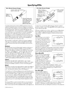
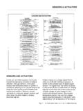
1 Bulletin E7000 rev01 01/06/97. SPECIFICATIONS ON HOW TO CHOOSE . AND USE FLAME SENSORS. SUPERVISION FLAME DETECTION CIRCUIT. All our FLAME detection systems utilize either an electrode or UV The FLAME sensor is powered by the two signal power lines obtained scanner as FLAME sensor . The FLAME sensor circuit has a voltage of from a transformer-separator allowing the FLAME sensor to operate 300 Vac to which a direct current component must be added during either on 115V or 230 Vac. Moreover it solves the problems of the FLAME detection.
2 The input circuit adequately filters the continuous phase-to-neutral and phase-to-phase systems. The FLAME sensor has voltage and amplifies its signal in order to pilot either mechanical or no power line. optical couplers which interface the detection system to the control circuit. These circuits are always independent to guarantee maximum operational safety and protection from electromagnetic fields. FLAME sensor LINES. Due to the low voltage of FLAME sensors, some measures must be Unipolar cables should be used, because they are best insulated taken to limit the precariousness of the FLAME detection system.
3 Here (>50 MW @ 300V-50Hz) and have lower capacities. Any leakage are some principles to follow to obtain better results: path may affect the ionization current, attaining the same value. Heat-resistant, insulating, though not impregnating material Quite short cable lengths should be aimed at, standard cable should be used. The cable size is not significant, nevertheless a length being between 10 to 20 meters. If longer cables are diameter of over 1 mm2 is recommended and complies with the absolutely required follow the following instructions carefully.
4 UV- directives concerning FLAME sensors. Shielded cables are not tubes allow for a little longer cables. 30 to 40 meter long cables recommended; multipolar cables must not be used. do not cause problems. Over 100 meter long cables are not common, therefore specific trials should be made in operating The ignition device may affect FLAME detection, therefore high conditions to test their efficiency. voltage cables to spark plugs or spark electrodes should be as short as possible. Spark electrodes should be installed as far away Cables should be laid in pipes and sheathes as far away as possible as possible from FLAME rods.
5 The two circuits should be from other leads and power cords. Pipes and sheathes should be independent. metallic and earthed, according to directives. If there are many Inverting the connections on the primary side of the ignition detection lines it is better not to group too many different leads in transformer may be useful, especially when a decrease in the the same pipe; it is better to use more than one pipe or spacer. ionization current occurs during ignition. Systems using one electrode for ignition and detection do not have this kind of problems.
6 Headquarters International Sales Esa Pyronics International Via E. Fermi 40 I-24035 Curno (BG) - Italy Zoning Ind., 4 me rue B-6040 Jumet - Belgium Tel. + - Fax + Tel + - Fax + - Bulletin E7000 rev01 01/06/97. MAX. RECOMMENDED LENGTHS FOR FLAME DETECTION THROUGH ELECTRODE. sensor LINE AND INSULATING MATERIAL. An electrode (in KANTAL or GLOBAR) immersed in the FLAME may be MATERIAL MAX. LENGTH TEMP. used as a FLAME sensor for FLAME detection in gas systems in order to (m) ( C) exploit the ionizating effect of the FLAME . PVC (polyvinyl chloride) The intensity of the ionization current generally increases in VINOFLEX-VESTOLIT-HOSTALIT-VINNOL < 50 - 50 + 105 connection to the gas calorific power and to the FLAME temperature.
7 PE (polyethylene) Another very important factor is the air/gas ratio: an excess of gas LUPOLEN-HOSTALEN-VESTOLEN < 100 - 70 + 80 produces very low signals; an excess of air produces moderately high PA (polyamid) signals. NYLON-RILSAN * - 55 + 105 Those who want to calibrate the burner by controlling the FLAME PP (polypropylene) signal (only through an electrode) will obtain best results by HOSTALEN PP-NOVOLEN-VESTOLEN < 100 - 10 + 90 adjusting the air so as to increase the ionization current to its PTFE (polytetrafluorethylene) maximum and then increasing the quantity of air until the FLAME TEFLON-FUON-HOSTAFLON < 100 - 100 + 260 signal slightly decreases.
8 PVF 2 (polyvinylfluorid) The electrode must be detached from the metallic case of the burner. KYNAR * - 30 + 150 The FLAME must always touch the electrode during the whole EFTE (copolymer of PTFE) operation. TEFZEL < 100 - 100 + 150 Usually the surface of the metallic case touched by the FLAME is 4 to PCTFE (ECTFE polychlortrifluorethylene) 5 times the surface of the electrode immersed in the FLAME . FLAME HALON-POLIFLUORON < 100 - 40 + 150 detection with two electrodes is impossible. Should the area of the PI (polyamid) burner touched by the FLAME be insufficient, additional surfaces may KAPTON < 80 - 90 + 275 be added, such as blades or small plates welded to the frame.
9 PUR (polyurethan) When one electrode is used both for ignition and detection, make VULKOLLAN-CAPROLAN-DESMOPAN * - 60 + 90 sure it is adequately insulated and there are no discharges on the PS (polystyrene) surface, or between the flanges, because they may result in a non NOVODUR-LURAN-HOSTYREN-VESTYREN < 100 - 0 + 65 perfect FLAME detection system. SiR (silicone rubber) The FLAME signal should always be stable; wide fluctuations are SILOPREN-SILIKON < 100 - 60 + 180 symptomatic either of a malfunctioning electrode or burner, or of SBR (styrene butadiene rubber) unbalances caused by an inadequate positioning of the FLAME sensor BUNA < 20 - 30 + 60 line or of insulation defects.
10 IIR (butyl rubber) Make sure the system works correctly over the all range of operating ENJAY-BUTYL < 40 - 60 + 100 temperatures, as the characteristics of some material change when CR (polichloroprene) the temperature increases. NEOPRENE-BAYPREN * - 40 + 60. CSM. HYPALON * - 30 + 100. ethylene polymer and vinyl acetate LEVAPRENE < 20 - 0 + 120. * ABSOLUTELY DISCOURAGED. 2/3. Bulletin E7000 rev01 01/06/97. DETECTION THROUGH UV-TUBE. The signals originated by the UV-tube are higher than the ones When mounting the detector it should be observed that it is directed originated by the electrode.