Transcription of Speed Control of Induction Motor using PWM Technique
1 Speed Control of Induction Motor using PWM Technique Prof. Harsha P. Pawar, Assistant Professor,Department of Electronics and telecommunication Engineering; Dr. DaulatraoAher college ofEngineering,Karad, Dist-SATARA; Maharashtra , India Miss. Neha S. Chavan.,Miss. Ashwini B. Shinde and Miss. Yugandhara S. Chavan, student, Department of Electronics and telecommunication Engineering; Dr. DaulatraoAher college ofEngineering, Karad, Dist-SATARA; Maharashtra, India Abstract- Speed Control of Induction Motor is a new Technique . It has high-efficiency which drives ac Induction Motor with PWM modulated sinusoidal voltage and design of a low operation is controlled by using 8051 family microcontroller. The circuit is capable of supplying single phase Induction Motor with varying ac mains ac voltage is directly modulated.
2 It requires a lower number of active and passive components which compared with costly converter. This proposed Control Technique is use in consumer and industrial products like washing machine, dishwashers, ventilators, compressors. Index Term- Microcontroller89S52,Optocoupler, Induction Motor , Speed Control . Induction Motor are widely used in industrial ,commercial ,utility application, residential application. It is used in various applications because the Motor have low cost, high efficiency, wide Speed range and robustness[1].In the present time, in the most of the applications, AC machines are useful than DC machines due to their simple and most robust construction without any mechanical commutators.
3 Motor Control applications span everything from residential washing machines, fans, and automotive window lift, traction Control systems and various industrial drives. In many industrial applications in which Induction Motor are fed by static frequency inverters is growing fast. Thus electric Motor is most important component. A complete production unit have three basic component driven (working) machine, transmitting device and electric Motor . An electric Motor is source of power. Power from electric Motor to driven is delivered by transmitting device. The electric Motor is classified as : 1. AC Motor . 2. DC Motor . In this project paper microcontroller based system to Control Speed of Induction Motor is developed using pulse width modulation Technique [2].
4 The electric Motor Speed is fixed when AC Motor is connected to AC line. Speed is calculated by: Ns =120*f/p-slip Ns= Motor Speed , f=frequency, p= number of poles. Now Speed of Motor need to be change in many application[3]. So pulse width modulation Technique is more efficient and pulse width modulation Technique provides higher level of performance. Speed of Motor can be adjusted by changing the frequency applied to Motor [1]. II. METHODOLOGY. PRINCIPLE This project attempts a new Speed Control Technique for single phase AC Induction Motor . It has low cost, high efficiency drive capable of supplying a single phase Induction Motor with PWM modulated sinusoidal voltage. The circuit operation Control by an 8051 family microcontroller[4].
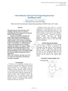
5 The device is aimed at substituting commonly used TRIAC phase angle Control drives. The circuit is capable of supplying single phase Induction Motor (inductive or resistive load) with varying AC voltage. B. BLOCK DIAGRAM Figure 1. Block Diagram of Speed Control Of Induction Motor using PWM Technique . International Journal of Engineering Research & Technology (IJERT)ISSN: (This work is licensed under a Creative Commons Attribution International License.)Vol. 4 Issue 04, April-2015174It is same as in TRIAC Control , the voltage applied to load can be varied from zero to maximum value. On the other side, a pulse width modulation Technique (PWM) is used and it is compared with the phase angle Control and used for TRIAC, it produces much lower high order harmonics.
6 Because the circuit is aimed at low-cost, medium-power applications, to produce the output voltage waveform it does not use a conventional converter topology[5]. It modulates the mains AC voltage. As compared with costly converter, it requires minimum number of active and passive power components. The device attempted here takes advantage of both the low cost of the phase angle Control and the minimum harmonic content and greater efficiency which get standard converter topology. The drive uses a PWM controlled MOSFET then the load in series with a bridge rectifier. This drive based on this proposed Control Technique is used in consumer and industrial products like fan, washing machine, dishwashers, ventilators The input terminals of the rectifying bridge are connected in series with load.
7 The output terminals (rectified side) has power transistor (IGBT, MOSFET or bipolar) connected across them. Current cannot flow through the rectifying bridge whenthe power transistor is off then the load which is in series and remains in an off-state. The bridge output terminals are short-circuited, when the power transistor is on and then current can flow through the rectifying bridge and thus through the load. The power to the load is controlled by changing the duty cycle of PWM pulses. Thus the special care is taken by the circuit such that the PWM pulses are synchronized with the supply phase by zero voltage sensing point. SYSTEM : The 89c52 is commonly used microcontroller have 8K byte program The AT89S52 is a low-power, high-performance CMOS 8-bit microcontroller with 8K bytes of in-system programmable Flash memory.
8 The AT89S52 provides the following standard features: 8K bytes of Flash, 256 bytes of RAM, 32 I/O lines, Watchdog timer, two data pointers, three 16-bit timer/counters, a six-vector two-level interrupt architecture, a full duplex serial port, on-chip oscillator, and clock circuitry. In addition, the AT89S52 is designed with static logic for operation down to zero frequency and supports two software selectable power saving modes. The Idle Mode stops the CPU while allowing the RAM, timer/counters, serial port, and interrupt system to continue functioning. The Power-down mode saves the RAM contents but freezes the oscillator, disabling all other chip functions until the next interrupt or hardware reset.
9 (MOC3021): In this project we have an opto-coupler MOC3021 an LED diac type combination. Additionally while using this IC with microcontroller and one LED can be connected in series with IC LED to indicate when high is given from micro controller such that we can know that current is flowing in internal LED of the logic high is given current flows through LED from pin 1 to 2. So in this process LED light falls on DIAC causing 6 & 4 to close. During each half cycle current flows through gate, series resistor and through opto-diac for the main thyristor / triac to trigger for the load to operate. The opto-coupler usually found in switch mode power supply circuit in many electronic equipment.
10 It is connected in between the primary and secondary section of power supplies. : An SCR consists of four layers of alternating P and N type semiconductor materials. Silicon is used as the intrinsic semiconductor, to which the proper dopants are added. The junctions are either diffused or alloyed. The planar construction is used for low power SCRs (and all the junctions are diffused). The mesa type construction is used for high power SCRs. In this case, junction J2 is obtained by the diffusion method and then the outer two layers are alloyed to it, since the PNPN pellet is required to handle large currents.