Transcription of SPEED CONTROL SYSTEM - Pneumax
1 DKM CO.,LTD. 143 SPEED CONTROL SPEED CONTROL SYSTEM INDEXSPEED CONTROL motor FEATURES1446W ( 70mm)15310W ( 70mm)15515W ( 80mm)15725W ( 80mm)15940W ( 90mm)16160W ( 90mm)16390W ( 90mm)165120W ( 90mm)168180W ( 90mm)171 144 DKM CO., motor allow you to easily set and adjust the SPEED . DKM motor offers three kinds of AC SPEED CONTROL as shown below. Select the best SYSTEM depending upon your application. DIGITAL TYPE (CONNECTOR Type / Digital Display)FX1000A Series UNIT TYPE (CONNECTOR Type)DSA Series SOCKET TYPE DSK Series Features of SPEED CONTROL MotorDSK ControllerDSKS ControllerDKM CO.
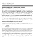
2 ,LTD. 145 SPEED -Torque Characteristics of SPEED CONTROL SystemsThe SPEED -torque characteristics line of all AC SPEED CONTROL motors characteristics is shown in the figure set SPEED changes slightly according to the change in load torque. Safe Operation Line and Permissible Torque When Using a GearheadInput power to the SPEED CONTROL motor depends on the load and SPEED . The greater the load, and the lower the SPEED , thegreater an increase in motor the SPEED -torque characteristics graph, the line is referred to as the safeoperation line, while the area below the line is called the continuous operation safe operation line, measured according to motor temperature, indicates its operational limit for continuous usage withthe temperature.
3 Whether the motor can be operated at a specific torque and SPEED is determined by measuring thetemperature of the motor case. In general, if the motor 's case temperature is below 90 (194 ), continuous operation ispossible, considering the insulation class of motor coil winding. But the motor life could be extended with lower motortemperature. So it is recommended that the motor be used under conditions that keep the motor temperature has two kinds of cooling fan ; General fna (F type) and Powerful fan (F2 type). F fan is attached in motor shaft and itsspeed depends on the motor shaft SPEED . So in slow SPEED of motor , there is very weak cooling effect.
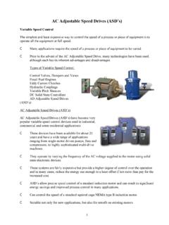
4 In the applicationwhere motor SPEED should be changed from low SPEED (below 1,000 rpm) to hight SPEED like SPEED CONTROL motor , F2 fan isneeded so that cooling effect keep constantly regardless of the motor case of SPEED CONTROL motor and inverter motor , DKM is employing F2 type fan into them basically. ; In special applicationor by user s request F type fan can be employed in SPEED CONTROL motor and inverter motor . And please be advised that in all motors, F2 fan can be attached by user s CONTROL Technical Reference SPEED CONTROL Methods of SPEED CONTROL Systems By a potentiometer, the SPEED setting voltage is supplied.
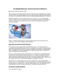
5 The motors SPEED is sensed and the SPEED signal voltage is supplied. The difference between the SPEED setting voltage and SPEED signal voltage is supplied. A voltage determined by the output from the capacitor is supplied to the motor so that it will reach the set SPEED . 145-1 DKM CO., FX1000A series combines a CONTROL unit and AC SPEED Controlmotor. Connection between the motor and CONTROL Unit is simplifiedby an easy-to-use connector. Digital Type SPEED CONTROL MotorFX1000A CONTROL SYSTEM Features Easy Connection CONTROL units combine the CONTROL pack, potentiometer and capacitor into one device. Operation is possible just by connectingthe CONTROL unit into power supply after connecting the motor and CONTROL unit together using the connector.
6 Easy Operation The SPEED can be set easily with the potentiometer on the front panel of the CONTROL unit. DIGIRAL DISPLAY The motor SPEED can see directly on the front panel of display of the CONTROL unit. SYSTEM ConfigurationExtension Cables (Accessories)( Page 236 )Clutch & BrakeMotor Mounting Plate (Accessories)( Page 234)FX1000A ControllerCapacitorACPowerSupplyWorm solid typeWorm hollow typeDKM CO.,LTD. 145-2 SPEED CONTROL ItemDetailRated Input Voltage220 VAC 50/60 HzWorkable Voltagefrom -15% to +10% of 220 VACC onsumption PowerLess than 4 VAControl ModePhase Loop CONTROL (0 to 220 VAC)Input Frequency10Hz ~ 360Hz (TACHO)Power On-Off SignalRed color of LED SPEED Set Range100 ~ 1750(RPM)Ambient Temperaturefrom -10 to +55 Ambient Humidity35 ~ 85% RHWeight300gDimension60(w) x 100(h) x 92(d)
7 MmInsulation Resistance100 or more when 500V mega is applied between the windings and the housing after rated motoroperation under normal ambient temperature and humidity Dielectric StrenghtSufficient to withstand at 50/60Hz applied between the windings and the case after rated motoroperation under normal ambient temperature and humidity for III FX1000A Controller Specification General Specification motor capacity / Rated CurrentSpecificationOutputCapacitorRated Current7 SDGC - - - - - - - - - CO.,LTD. Dimension Circuit DiagramDKM CO.,LTD. 145-4 Terminal TypeNo FanPowerful Fan(CAPACITOR)(CAPACITOR) Connector Type Operation Method : At first connect each terminal on the rear panel of the controller with the motor as instructed in connection diagram.
8 And theninput the external power to both of the terminal AC for the rated SPEED operation. Now you can adjust the main volume on the center of front panelto CONTROL the output SPEED of motor as user want. * Direction : CW : (CW+COM) CCW : (CCW+COM)* Capacitor : Connect (9-6) or (9-3) According to it s capacity* CW : (COM+CW)* CCW : (COM+CCW)200 - 240 V - 60 Hz 4VA! - (CAPACITOR) - (CAPACITOR)DKM CO.,LTD. 147 The DSK CONTROL SYSTEM combines a CONTROL unit and ACspeed CONTROL motor . Connection between the motor andcontrol unit is simplified by socket. Socket Type SPEED CONTROL MotorDSK CONTROL SYSTEM Features Compact SPEED CONTROL PackIt is compact SPEED CONTROL pack with small pulg-in (8 pin) type.
9 Easy OperationThe SPEED can be set easily with the potentiometer on the front panel of DSK model. In case of DSKS model, thepotentiometer ( SPEED CONTROL volume) could be separated from body. SYSTEM Configuration1. DSK controllerThe variable resistor for SPEED CONTROL is installed in front of body like belowMotorGearheadCapacitorSocketACPower SupplyDSK Controller2. DSKS controllerThe remote SPEED CONTROL is available by separate variable resistor like below. MotorGearheadCapacitorPotentiometerACPow erSupplyDSKS ControllerSPEED CONTROL (DSK Controller)(DSKS Controller) 148 DKM CO.,LTD. DSK(S) Controller Specification General Specification Dimension(1) DSK(2) DSKSItemDetailRated Input Voltage220 VAC 50/60 HzWorkable Voltagefrom -15% to +10% of 220 VACC onsumption PowerLess than 4 VAControl ModePhase Loop CONTROL (0 to 210 VAC)Power On-Off SignalRed color of LED Allowed RPM Range90 ~ 1750 RPMA mbient Temperaturefrom -10 to +55 Weight160gDSK (variable resistor installed) : 58(W) x 85(H) x 91(D)mmDSKS(variable resistor separated).
10 (W) x 77(H) x 100(D)mm100 or more when 500V mega is applied between the windings and the housing after rated motoroperation under normal ambient temperature and humidity Sufficient to withstand at 50/60Hz applied between the windings and the case after rated motoroperation under normal ambient temperature and humidity for 1min Insulation ResistanceDimensionDielectric StrengthDKM CO.,LTD. 149 Connection Diagrams For CCW operation, please change Red and blue. How to Read SpecificationsLead Wire Type7 SDG(S)A-6G7 SDG(S)B-6G7 SDG(S)C-6G7 SDG(S)D-6G7 SDG(S)E-6G7 SDG(S)F-6G------1/125 Single Phase 110 Single Phase 115 Single Phase 220 Single Phase 220 Single Phase 230 Single Phase 23060605060506090~170036036 20020 400 40 70432 43 240 24 480 48 360 36 200 20 400 40 432 43 240 24 480 48 360 36 200 20 400 40 73 90~140090~170090~140090~ Box TypeModel7 SDG -6G : Pinion Shaft Type7 SDS -6 : Round Shaft Maximum Output.