Transcription of SPITFIRE IX, XI & XVI PILOTS NOTES - Zenos …
1 SPITFIRE IX, XI & XVI PILOTS NOTES3rd Edition. This Edition supersedes all previous issuesBrought to you byZeno s Warbird Video Drive- World War II Aviation Videos Playing Live online 24/7 NOTES TO USERSTHIS publication is divided into five parts:Descriptive, Handling, Operating Data,Emergencies, and Illustrations. Part I gives onlya brief description of the controls with which thepilot should be NOTES arc complementary to 2095 Pilot's NOTES General and assume a thoroughknowledge of its contents. All PILOTS should be inpossession of a copy of 2095 ( )-Words in capital letters indicate the actualmarkings on the controls copies may be obtained by the StationPublications Officer by application on Form294A, in duplicate, to Command headquartersfor onward transmission to , 81 FulhamRoad, (see A.)
2 1114/44). Thenumber of this publication must be quoted infull 1565J, P & L and suggestions should be forwardedthrough the usual channels to the Air Ministry( ). AIR PUBLICATION 1565J, p & L Pilot's NOTES 3rd EditionSPITFIRE IX, XI & XVI PILOTS NOTES3rd Edition. This Edition supersedes all previous OF CONTENTSPART I DESCRIPTIVEINTRODUCTIONFUEL, OIL AND COOLANT SYSTEMSFuel tanks ..2 Fuel contents gauges and pressure warning coolant SERVICESH ydraulic system ..Electrical Pneumatic CONTROLST rimming tabs ..Undercarriage indicators Undercarriage warning ..Wheel brakes ..Flying controls locking MINISTRYS eptember CONTROLSPara,PART III-OPERATING 19 Propeller controlr * * 20 Supercharger controls 21 Intercooler 22 Radiator flap control.
3 23 Slow-running cut-out 24 Idle cut-off control ..i 25 Carburetor air intake filter control 26 Cylinder priming pumpi . 27 Ignition switches and starter buttons 28 Ground battery starting 29 OTHER CONTROLSC ockpit doorSliding hood controlsSignal dischargerEngine data Merlins 61, 63, 66, 70 and 266 51 Flying limitations 52 Position error corrections . 53 Maximum performance .. 54 Economical flying 55 Fuel capacities and consumption 56 PART IV EMERGENCIESU ndercarriage emergency operation 57 Failure of the pneumatic system 58 Hood jettisoning 59 Forced landing 60 Ditching 61 Crowbar
4 62 PART II HANDLINGM anagement of the fuel systemPreliminariesStarting the engine and warming up (Merlin 61and63 engines)Starting the engine and warming up (Merlin 66, 70and 266 engines)Testing the engine and servicesCheck list before take-offTake-offClimbingGeneral flyingStallingSpinningDivingAerobaticsCh eck list before landingApproach and landingMislandingBeam approachAfter landing333435363738394041424344454647484 950 PART V ILLUSTRATIONS panel 1 Cockpit port side 2 Cockpit starboard side 3 Fuel system diagram 4303132Am PUBLICATION 1565), P & L 's NotesPART IDESCRIPTIVENOTE.
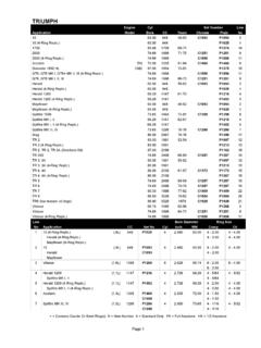
5 The numbers quoted in brackets after items in the textrefer to key numbers of the illustrations in Part V.'INTRODUCTION1. (i) The variants of the SPITFIRE IX, XI and XVI are dis-tinguished by prefix letters denoting the general operatingaltitude or role and the suffix letter (e) is used where 5-in. guns replace 303-in. guns. The aircraft are allessentially similar, but the following table shows the mainfeatures that give the various versions their distinguishingletters:F IXMerlin 61, 63 or 63A; two 20-mm. and four 303-in. IXMerlin 66; two 20-mm. and four LF IX (e) Merlin 66; two 20-mm. and two 5-in. guns. HF IX Merlin 70; two 20-mm. and four IX (e) Merlin 70; two 20-mm. and two 5-in. XI Merlin 61, 63, 63A or XVI Merlin 266; two 20-mm.
6 And two 5-in. guns.(ii) Merlin 61 and 63 engines have carburettors, buton Merlin 66, 70 and 266 engines these are replaced byBendix-Stromberg injection carburettors.(iii) All these marks of aircraft are fitted with Rotol 4-bladedhydraulic propellers and on the majority of the aircraft the wingtips are clipped.(iv) Later Mk. IX and XVIs have "rear view" fuselages whichincorporate "tear-drop" sliding I DESCRIPTIVEFUEL, OIL AND COOLANT SYSTEMS2. Fuel tanks (sec Fig. 4). Fuel is carried in two tanksmounted one above the other (the lower one is self-sealing) forward of the cockpit. The top tank feeds intothe bottom tank and fuel is delivered to the carburettor,through a filter, by an engine-driven pump.
7 On Merlin 61and 63 engine installations there is a fuel cooler, whileon Bendix-Stromberg carburettor installations a de-aerator in the carburettor, for separating accumulatedair from the fuel, is vented to the top tank. Later Mk. IXand all F. Mk. XVI aircraft mount two additional fueltanks with a combined capacity of 75 gallons (66 gallonsin aircraft with "rear view" fuselages); they arefitted in the fuselage behind the cockpit. These tanksshould only be filled for special operations at the discretionof the appropriate Area Commander and normally theircocks should be wired OFF. If fitted in aircraft with"rear view" fuselages, they must not be used in capacities of the main tanks are as follows:Top tank.
8 48 gallonsBottom gallons or 47* gallons or 95* gallons* On some aircraft; generally those which have "rear view" auxiliary "blister" drop tank of 30, 45 or 90 gallons capacity(on the PR XI, of 170 gallons capacity) can be fitted under thefuselage; the fuel from these tanks feeds the engine direct anddocs not replenish the main tanks. To meet the possibility ofengine cutting due to fuel boiling in warm weather at highaltitudes, the main tanks arc pressurised; pressurising, however,impairs the self-sealing properties of the tanks and should,therefore, be turned OFF if a tank is Fuel cocks. The cock control for the main tanks is alever (47) fitted below the engine starting pushbuttons7 PART I DESCRIPTIVEand the pressurising control (50) is below the right-hand side ofthe instrument panel.
9 The cock control (58) and jettison lever(59) for the auxiliary drop tank arc mounted together on theright-hand side of the cockpit, below the undercarriage controlunit. The jettison lever is pulled up to jettison the drop tank, butcannot be operated until the cock control is moved forward tothe OFF position. The cock for the rear fuselage tanks (whenfitted) is to the left of the Fuel pumps. On Bendix-Stromberg carburettor installationsan electric booster pump, operated by a switch on the left-handside of the cockpit, is fitted in the lower main tank. On earlyaircraft this pump is not fitted, but a hand wobble pump isprovided instead, just forward of the remote On aircraft which have rear fuselage tanks a secondpump is fitted (in the lower rear tank) and the controlswitch described above then has three Fuel contents gauges and pressure warning light.
10 Thecontents gauge(19)on the right-hand side of the instrumentpanel indicates the quantity of fuel in the lower main tank whenthe adjacent pushbutton is depressed. On aircraft with rearfuselage tanks a gauge (for the lower rear tank only) is mountedbeside the main tanks' gauge. This also operates when the maintanks' gauge pushbutton is depressed. On later Mk. XVIaircraft the two gauges are mounted together, the left-hand dial(which is calibrated only up to 50 gallons) indicating thecontents of the main fuel pressure warning light (18) is operative when theswitch (34) on the throttle quadrant is on and comes on at anytime when fuel pressure at the carburettor falls appreciablybelow Oil system. Oil is supplied by a tank of 75 gallons oilcapacity under the engine mounting, which is pressurisedto 21/2 , and passes through a filter before en-tering the engine.