Transcription of Split System Cooling Product and Performance Data XB 13
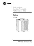
1 Split SystemCooling Product & Performance DataXB 132 TTB3018-0601 5 TonsPUB. NO. 22-1769-07 2012 Trane 2 22-1769-07 Features and Benefits Efficiency up to SEER All aluminum Spine Fin coil Fast, complete-drain, weatherproof base WeatherGuard fasteners Polyslate gray cabinet with anthracite gray badge and cap Quick-Sess cabinet, easy service access and refrigerant connections with full coil protection Glossy corrosion resistant finish Internal high/low pressure & temperature protection Comfort "R" Mode Approved 018, 024, 030, 042 & 048 ship with start kit Liquid line filter-drier Design Testing R-22 refrigerant 100% line run test Low ambient Cooling to 55 F as shipped Low ambient Cooling to 30 F with AY28X079 Low ambient Cooling to 0 F with BAYLOAM10322-1769-07 3 ContentsFeatures and Benefits 2 General data 4 Product Specifications 4A-weighted Sound Power Level [dB(A)]
2 ] 4 Accessory Description and Usage 5 AHRI Standard Capacity Rating Conditions 5 Model Nomenclature 6 Electrical data 7 Dimensions 12 Mechanical Specification Options 13 4 22-1769-07 Product SpecificationsModel No. 1 2 TTB3018A1000C 2 TTB3024A1000C 2 TTB3030A1000C 2 TTB3036A1000 CElectrical data V/Ph/Hz 2 200/230/1/60 200/230/1/60 200/230/1/60 208/230/1/60 Min Cir Ampacity 8 12 13 21 Max Fuse Size (Amps) 15 20 20 35 Compressor RECIP RECIP RECIP SCROLL RL Amps - LR Amps - - - 63 - 87 Outdoor Fan FL Amps HP 1/15 1/8 1/8 1/6 Fan Dia (inches) Spine Fin Spine Fin Spine Fin Spine Fin Refrigerant R-22 (Not factory supplied) 4/00-LB/OZ 5/02-LB/OZ 5/08-LB/OZ 6/05-LB/OZLine Size - (in.)
3 Gas 3 5/8 3/4 3/4 7/8 Line Size - (in.) Liquid 3 1/4 5/16 5/16 3/8 Dimensions H x W x D (Crated) x x 30 x x 30 38 x x 33 38 x x 33 Weight - Shipping 182 195 225 205 Weight - Net 163 175 197 178 Start Components YES YES YES NOSound Enclosure NO NO NO NOCompressor Sump Heat NO NO NO NOOptional Accessories: 4 Anti-short Cycle Timer TAYASCT501A TAYASCT501A TAYASCT501A TAYASCT501 AEvaporator Defrost Control A/C AY28X079 AY28X079 AY28X079 AY28X079 Rubber Isolator Kit BAYISLT101 BAYISLT101 BAYISLT101 BAYISLT101 Crank Case Heater Kit BAYCCHT300 BAYCCHT300 BAYCCHT300 BAYCCHT301 Hard Start Kit Scroll BAYKSKT260 Extreme Condition Mounting Kit BAYECMT001 BAYECMT001 BAYECMT001 BAYECMT001 Refrigerant Lineset 5 TAYREFLN1* TAYREFLN2* TAYREFLN2* TAYREFLN3*1 Certified in accordance with the Unitary
4 Air-Conditioner equipment certification program which is based on AHRI Standard 210/240. 2 Calculated in accordance with Use only HACR circuit breakes or fuses. 3 Standard line lengths - 60'. Standard lift - 60' Suction and Liquid line. For Greater lengths and lifts refer to refrigerant piping software Pub# 32-3312-0 . ( denotes latest revision) 4 For accessory description and usage, see page 5. 5 * = 15, 20, 25, 30, 40 and 50 foot lineset available. General DataA-weighted Sound Power Level [dB(A)]MODELSOUND POWER LEVEL [Db(a)]A-WEIGHTED FULL OCTAVE SOUND POWER LEVEL dB - [dB(A)] : Tested in accordance with AHRI Standard (Not listed with ARI)22-1769-07 5 General DataProduct SpecificationsModel No. 1 2 TTB3042A1000C 2 TTB3048A1000C 2 TTB3060A1000 CElectrical data V/Ph/Hz 2 200/230/1/60 200/230/1/60 208/230/1/60 Min Cir Ampacity 21 25 33 Max Fuse Size (Amps) 35 40 50 Compressor RECIP RECIP SCROLL RL Amps - LR Amps - - - 146 Outdoor Fan FL Amps HP 1/6 1/6 1/4 Fan Dia (inches) Spine Fin Spine Fin Spine Fin Refrigerant R-22 (Not factory supplied) 6/13-LB/OZ 8/14-LB/OZ 8/11-LB/OZLine Size - (in.)
5 Gas 3 7/8 1-1/8 1-1/8 Line Size - (in.) Liquid 3 3/8 3/8 3/8 Dimensions H x W x D (Crated) x x x x x x - Shipping 283 307 280 Weight - Net 249 271 244 Start Components YES YES NOSound Enclosure YES NO NOCompressor Sump Heat NO NO NOOptional Accessories: 4 Anti-short Cycle Timer TAYASCT501A TAYASCT501A TAYASCT501 AEvaporator Defrost Control A/C AY28X079 AY28X079 AY28X079 Rubber Isolator Kit BAYISLT101 BAYISLT101 BAYISLT101 Crank Case Heater Kit BAYCCHT300 BAYCCHT300 BAYCCHT300 Hard Start Kit Scroll BAYKSKT263 Extreme Condition Mounting Kit BAYECMT001 BAYECMT001 BAYECMT001 Refrigerant Lineset 5 TAYREFLN3* TAYREFLN4* TAYREFLN4*AHRI Standard Capacity Rating ConditionsAHRI STANDARD 210/240 RATING CONDITIONS (A) Cooling 80 F DB, 67 F WB air entering indoor coil, 95 F DB air entering outdoor coil.
6 (B) High Temperature Heating 47 F DB, 43 F WB air entering outdoor coil, 70 F DB air entering indoor coil.(C) Low Temperature Heating 17 F DB, 15 F WB air entering outdoor coil, 70 F DB air entering indoor coil.(D) Rated indoor airflow for heating is the same as for Cooling . AHRI STANDARD 270 RATING CONDITIONS (Noise rating numbers are determined with the unit in Cooling opera-tion.) Standard Noise Rating number is at 95 F outdoor Description and UsageAnti-Short Cycle Timer Solid state timing device that prevents compressor recycling until 5 minutes have elapsed after satisfying call or power interruptions. Use in area with questionable power delivery, commercial applications, long lineset, Defrost Control SPST Temperature actuated switch that cycles the condenser off as indoor coil reaches freeze-up conditions. Used for low ambient Cooling to 30 F with Isolators 5 large rubber donuts to isolate con-densing unit from transmitting energy into mounting frame or pad.
7 Use on any application where sound transmission needs to be Start kit Start capacitor and relay to assist compres-sor motor startup. Use in areas with marginal power supply, on long linesets, low ambient conditions, Condition Mount Kit Bracket kits to securely mount condensing unit to a frame or pad without removing any panels. Use in areas with high winds, or on commercial roof tops, etc. 6 22-1769-07T U D 1 B 0 8 0 A 9 H 3 1 A AFurnace ConfigurationTU = Upflow/HorizontalTD = Downflow/HorizontalTypeE = 80% Induced Draft StandardD = 80% Induced Draft PremiumC = 90% Condensing StandardX = 90% Condensing PremiumH = 95% Condensing PremiumNumber of Heating Stages1 = Single Stage2 = Two StageM = ModulatingMajor Design ChangeMinor Design ChangeService Digit - Not OrderableHeating Input in 1000 s (BTUH)
8 080 = 80,000 BTUHC abinet WidthA = " Cabinet WidthB = " Cabinet WidthC = " Cabinet WidthD = " Cabinet WidthAir Capacity for CoolingStandard PSC Variable Speed High Efficiency24 = 2 To ns V3 = 3 To ns H3 = 3 To ns36 = 3 To ns V4 = 4 To ns H4 = 4 To ns42 = To ns V5 = 5 To ns H5 = 5 To ns45 = 4 To ns48 = 4 To ns54 = 5 To ns60 = 5 To ns72 = 6 To nsVoltage9 = 115 Volts / 60 Hertz / Natural GasA = 115 Volts / 50 Hertz / Natural GasC = 115 Volts / Natural Gas with Communicating System ControlF = 115 Volts / Natural Gas with Integrated Electronic FilterD = 115 Volts / Natural Gas with Communicating System Control and Integrated Electronic FilterDraft Inducer Speeds1 = Single Speed2 = Two SpeedV = Variable SpeedGas FurnacesG A M 5 A 0 B 3 6 M 3 1 S A ABrandT = BetterG = Good Product TypeA = Air HandlerProduct Tier2 = Good, Entry Level Feature Set4 = Better, Retail Replacement Mid = Better, Entry Level High Effy.
9 , Multi-Speed7 = Best, Retail Replacement High Effy., Variable-Speed8 = Best, Retail Ultimate High Effy., Variable-SpeedMajor Design ChangeMinor Design ChangeUnit Parts IdentifierAirflow Type & CapabilityS = Low Effy PSC, 1-5 - nom. Tonnage (cfm/ton)M = Mid Effy Multi-Speed, 1-5 - nom. To nnage (cfm/ton)H = High Effy Multi-Speed, 1-5 - nom. To nnage (cfm/ton)V = High Effy Variable, 1-5 - nom. To nnage (cfm/ton)No Descriptor0 = Air Handler / CoilSystem Control TypeS = Standard - 24 VACC = CLII VDCSize (Footprint)A = x = x = x Size: Air Handler or Coil0-9 = AH Coil - 1000 BTU s (18, 24, 30, 36, 42, 48, 60)Power Supply1 = 208-230/1/60 ConvertabilityM = Multi-poise 4-wayF = Upflow Front Return, 3-wayT = 3-wayAir Handler4 T X C B 0 3 6 A C 3 H C A ASeriesT = Premium (Heat Pump or Convertible Coil)C = Standard ( Cooling Only)Refrigerant Type4 = R-410 ACoil DesignX = Direct Expansion Evaporator CoilCoil FeatureC = Cased A CoilA = Uncased A CoilF = Cased Horizontal Flat CoilCoil Width (Cased/Uncased)A = " "B = " / "C = " / "D = " / "H = "Refrigerant Line Coupling0 = BrazedNominal Capacity in 1000's (BTUH)Major Design ChangeEfficiencyC = StandardS = Hi Efficiency (derived from 10 SEER products)
10 Refrigerant Control3 = TXV - Non-BleedCoil CircuitryH = Heat PumpC = CoolingAirflow ConfigurationA = Upflow OnlyU = Upflow / DownflowH = Horizontal OnlyC = Convertible - Upflow, Downflow, Left or Right AirflowMinor Design ChangeService Digit - Not OrderableHeat Pump/ Cooling CoilsModel NomenclatureRefrigerant Type2 = R-224 = R-410 ATRANEP roduct TypeW = Split Heat PumpT = Split CoolingProduct FamilyZ = Leadership Two StageX = LeadershipR = Replacement/RetailM or B = BasicA = Light CommercialFamily SEER0 = 10 3 = 13 6 = 161 = 11 4 = 14 8 = 182 = 12 5 = 15 9 = 19 Split System Connections 1-6 Tons0 = BrazedNominal Capacity in 000s of BTUsMajor Design ModificationsPower Supply1 = 200-230/1/60 or 208-230/1/603 = 200-230/3/604 = 460/3/60 Secondary FunctionMinor Design ModificationsUnit Parts IdentifierOutdoor Units2 TTB3036A1000AA22-1769-07 7 Electrical DataSchematic Diagrams(SEE LEGEND)