Transcription of SPROCKET AND CHAIN GUIDE - REV Robotics
1 SPROCKET GUIDE Created by REV Robotics 2016, Licensed Under CC BY-SA 1 fg SPROCKET AND CHAIN GUIDE SPROCKET GUIDE Created by REV Robotics 2016, Licensed Under CC BY-SA 2 TABLE OF CONTENTS 1 SPROCKET BASICS .. 3 Anatomy of a SPROCKET .. 3 Anatomy of CHAIN .. 4 Custom Length CHAIN .. 4 Master Links .. 5 Torque, Speed, and Power .. 6 Compound Gearing .. 10 2 REV SPROCKET SPECIFICATIONS .. 11 REV Robotics Sprockets .. 11 SPROCKET Mounting Pattern .. 15 SPROCKET Alignment Mark .. 15 SPROCKET Measurements .. 16 3 ALL SPROCKETS (1:1 Scale) .. 17 SPROCKET GUIDE Created by REV Robotics 2016, Licensed Under CC BY-SA 3 1 SPROCKET BASICS Sprockets are rotating parts with teeth that are used in conjunction with a CHAIN and, almost always, at least one other SPROCKET to transmit torque.
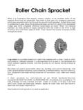
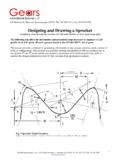
2 Sprockets and CHAIN can be used to change the speed, torque, or original direction of a motor. In order for sprockets and CHAIN to be compatible with each other they must both have the same thickness and pitch. In order for the sprockets and CHAIN to work effectively, all of the sprockets should be on parallel shafts with their corresponding teeth on the same plane. Anatomy of a SPROCKET The most common and important features of a SPROCKET are called out in Figure 1. Figure 1: Basic SPROCKET Nomenclature Number of Teeth is the total count of the number of teeth (projections) around the whole circumference of a SPROCKET . For sprockets with very few teeth it is easy to simply count the number of teeth. However, for sprockets with a higher number of teeth, attempting to count the teeth may not be very practical or accurate.
3 For our REV gears, we have taken all of the guesswork out of this process. Simply use the ALL SPROCKETS (1:1 Scale) reference GUIDE on page 17 by printing that page out at full scale and then match your SPROCKET to its correct outline on the page to identify the SPROCKET . Pitch Diameter (PD) is an imaginary circle which is traced by the center of the CHAIN pins when the SPROCKET rotates while meshed with a CHAIN . The ratio of the pitch diameter between sprockets can be used to calculate the gear ratio, but more commonly and much more simply the ratio of the number of teeth is used for this calculation. Pitch represents the amount of pitch diameter in inches per tooth. Gears with a larger pitch will have bigger teeth. Common pitches are , known as #25, and (#35).
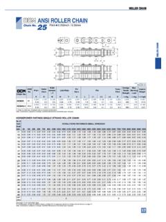
4 The REV Robotics building system uses #25 CHAIN . Outside Diameter (OD) will always be larger than the pitch diameter but smaller than the CHAIN clearance diameter. The outside diameter does not account for the additional diameter added by the CHAIN , so it should not be used to check for assembly interference. CHAIN Clearance Diameter is the outside diameter of a SPROCKET with CHAIN wrapped around it. The CHAIN clearance diameter will always be larger than the pitch diameter and the outside diameter. The CHAIN clearance diameter should be used when checking for interference when placing sprockets very close to other structures. SPROCKET GUIDE Created by REV Robotics 2016, Licensed Under CC BY-SA 4 Anatomy of CHAIN roller CHAIN is used to connect two sprockets together and transfer torque.
5 roller CHAIN is made up of a series of inner and outer links connected together to form a flexible strand (Figure 2). Figure 2: Basic CHAIN Nomenclature Outside Links consist of two outside plates which are connected by two pins that are pressed into each plate. The pins in the outside link go through the inside of the hollow bushings when the inner and outer links are assembled. The pins can freely spin on the inside of the bushings. Inside Link consist of two inside plates that are connected by two hollow bushings which are pressed into each plate. The teeth of the SPROCKET contact the surface of the bushings when the CHAIN is wrapped around a SPROCKET . Pitch is the distance between the centers of two adjacent pins. Common pitches are , known as #25, and (#35).
6 The REV Robotics building system uses #25 CHAIN . Custom Length CHAIN In almost all applications, CHAIN links are connected to form a loop. While CHAIN can sometimes be purchased in specific length loops, it is more common and economical to buy CHAIN by the foot and make custom loop lengths to fit the application. It is recommended to use a specialized tool, called a CHAIN breaker, to cut CHAIN into desired lengths in order to prevent accidental damage. See Table 1 for tool recommendations. Table 1: Recommended CHAIN Breaker Tools Tool Suppliers Approx. Cost DarkSoul CHAIN Break Dave s Discount Motors Various $ USD T-Handle roller CHAIN Break McMaster-Carr Amazon Various $15 - USD TETRIX MAX CHAIN Breaker Tool Pitsco <$ USD SPROCKET GUIDE Created by REV Robotics 2016, Licensed Under CC BY-SA 5 CHAIN breakers do not actually cut the CHAIN , instead they are used to press out the pins from an outer link.
7 After the pins have been removed the CHAIN can be separated leaving inner links on both ends of the break. Refer to individual tool instructions for more specific and detailed CHAIN break procedures. Master Links roller CHAIN is typically connected into a continuous loop. This can be done using a special tool to press the pins in and out of the desired outer link as described in the Custom Length CHAIN section, or if the CHAIN is already the correct length, an accessory called a master link, or quick-release link, (Figure 3) can be used to connect two ends of the CHAIN . Figure 3: Master Link (Enlarged) Master links allow for easy CHAIN assembly/disassembly without any special CHAIN tools. Master links can typically be reused many times, but will eventually become bent after repeated uses and should then be discarded.
8 Master links replace an outside link in a section of CHAIN , but before examining the master link connecting two sections of CHAIN , Figure 4 depicts the basic operation for assembling a master link. 1. Place the loose outer plate onto the two pins pressed into the other outer plate. 2. Ensure the outer plate is inserted onto the pins far enough that the grooves on the pins are fully exposed past the outer plate. 3. Align the widest gap near the middle of the clip with one of the pins. 4. The gap in the clip should allow the clip to slip over the pin and sit flush against the outer plate and aligned with the groove in the pins. 5. Use pliers or another tool to slide the clip towards the other pin until the clip is securely engaged with the grooves on both pins.
9 Figure 4: Master Link Detailed Assembly for Reference Installing the clip as shown in Steps 4 and Step 5 of Figure 4 can be sometimes difficult. There are a number of approaches that may work for these steps, but a common method is to use a pair of needle nose pliers to grip between the back of the clip and the nearest pin to slide the clip (Figure 5). Figure 5: Installing the Maser Link Clip with Pliers SPROCKET GUIDE Created by REV Robotics 2016, Licensed Under CC BY-SA 6 Master links are used to connect two ends of a section of CHAIN to create a loop of CHAIN . In order to use a master link, the CHAIN ends should both terminate with inside links (Figure 6). Slide the two pins from the master link into the rollers of the two terminating inside links.
10 Follow the procedure from Figure 4 to complete the link installation. Figure 6: Master Link Assembly on CHAIN Torque, Speed, and Power Sprockets are one common way to transmit power and change the output torque or speed of a mechanical system. Understanding of these basic concepts is required to make optimized design decisions. This section with briefly cover the definition of these concepts and then explain them in relationship to basic SPROCKET and CHAIN designs. Speed is the measure of how fast an object is moving. The speed of an object is how far it will travel in a given amount of time. For rotating parts like sprockets and wheels, speed is expressed in how many revolutions are made in a given amount of time. This rotational speed can be converted into linear speed at the edge of the SPROCKET by multiplying the pitch diameter by the rotations for a given time.