Transcription of SQM5… Reversing Actuator with Analog Input Signal
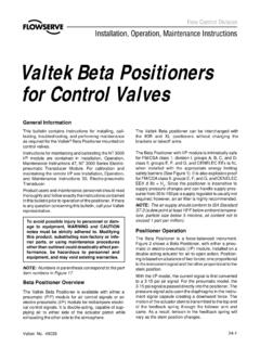
1 Installation InstructionsDocument No. 129-400 June 1, 2005 Reversing Actuator with Analog Input Signal Product Description Reversing Actuator used to position flow control valves, butterfly valves, dampers, or any application requiring rotary motion with an Analog Input Signal . Product Numbers for 4 to 20 mA Input Signal for 0 to 135 ohm Input Signal for 0 to 10 Vdc Input Signal Actuator Torque: 90 in/lb 90 in/lb 140 in/lb 200 in/lb 310 in/lb 400 in/lb Max Shaft Torque: 200 in/lb 220 in/lb 270 in/lb 400 in/lb motors allow torque on either end of the and shafts.
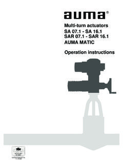
2 NOTE: For detailed information, see Technical Instructions 155-517P25. Caution Notations CAUTION: Equipment damage may occur if procedures are not followed as specified. Installation Cover Removal Use a Phillips screwdriver to loosen the two screws on the Actuator cover corners. See Figure 1. Lift the screws and raise the cover. See Figure 2. EA0564R1 EA0568R1 Figure 1. Figure 2. Rotational Direction Verification Actuator model numbers that end with R are factory configured for clockwise (cw), minimum to maximum rotation when facing the gear end of the Actuator , or counterclockwise (ccw) rotation when facing the other end of the Actuator .
3 The gear end of the Actuator is the side opposite of the visual position indicator. Actuator Mounting actuators can be mounted in any orientation. Optional base mounting brackets are available. actuators can also be face-mounted using self-tapping screws in combination with the various holes on the face of the Actuator gear end. Switch Adjustment are factory-wired with Switch I (maximum), Switch II (fully closed/economy position) and Switch III (minimum/low-fire). The individual switch cams I, II, and III are factory set to 90 , 0 and 10 , respectively. See Figures 3 and 4.
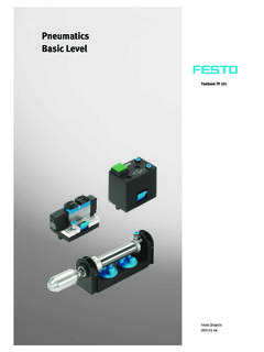
4 Item Number 129-400, Rev. 010 Page 1 of 5 Document No. 129-400 Installation Instructions June 1, 2005 10030500010030505010100307001003050 CAM DRUMRELEASE BUTTONGEAR ENDEA0561R3 ACTUATORPOSITION SCALESWITCH CAM ISET AT MAXIMUMSWITCH CAM IISET AT ZERO ("ECONOMY")SWITCH CAM IIISET AT MINIMUMACTUATOR POSITIONINDICATING POINTERCAM (1000 Ohm)FEEDBACK POTENTIOMETERDIAL POINTERACTUATOR POSITIONINDICATING DIALSINGLE SWITCHCAM POINTERDOUBLE SWITCH CAM POINTER Figure 3. Component Identification on the Cam Drum Side of the NOTE: The single switch cam pointers are used together with the black scales when configured for ccw operation.
5 The double switch cam pointers are used together with the red scales when configured for cw operation. The individual switch cams can be adjusted by hand or with the use of the tool attached to the outside of the hinged switch terminal protection lid. The adjustable range of the switches is limited by the potentiometer range. actuators have a 90 potentiometer and the switches must be adjusted between 0 and 90 . actuators have a 135 potentiometer and the switches must be adjusted between 0 and 135 . Shaft Adjustment The Actuator shaft can be disengaged by pressing the silver shaft release button.
6 The shaft release button is located above the grounding screw, under the hinged terminal protection cover, and to the right of the auto/manual switch. After pressing the shaft release button in and slightly upward, the shaft can be manually rotated. After the shaft has been manually aligned to the closed position, re-engage the shaft by pushing the shaft release button downwards. Cam Drum Adjustment Once the shaft has been set to the closed position, the cam drum must be manually aligned by pressing and holding the black cam drum release button (see Figure 3). Rotate the cam drum until the 0 mark on the Actuator position scale (left scale on the cam drum) is aligned with the gray Actuator position indicating pointer.
7 Position Indicating Dial Adjustment The actual position of the Actuator is indicated by the gray Actuator position indicating pointer (see Figure 3). The position is also displayed by the indicating dial through the housing s window. Ensure that the Actuator position indicating dial is aligned with the Actuator position scale. If necessary, rotate the dial in the clockwise direction. CAUTION: Turning the dial in the counterclockwise direction may loosen the potentiometer locking screw. Page 2 of 5 Siemens Building Technologies, Inc. Document No. 129-400 Installation Instructions June 1, 2005 Electrical Connection actuators are equipped with two removable conduit connection plates located on the upper corner of the gear housing.
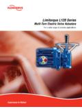
8 Each plate is provided with two threaded connections for 1/2-inch NPSM conduit connectors. The use of flexible 14 gauge or smaller stranded wire is recommended. NOTE: Actuators require a single-source, single-phase power supply. Grounding To avoid electro-magnetic interference, actuators must be grounded. The ground screw is located to the right of the AUTO/MAN switch (below the shaft release button). CAUTION: Disconnect the circuit board wire marked 51 during high voltage testing. Reconnect it to the grounding terminal after the test. leadsLRZL13NY+Y-UMYMY(+2 V) VRWBMANAUTO shown inauto (1000 Ohm)bacfor ccwrotationbrownblackblue"Economy"/Fully closedMinimum/Low fireMaximum/High ("G" board mA) ("K" board V)135 ("H" board0-135 Ohm) Figure 4.
9 Basic Functional Diagram of + "G" Board4 to 20mA "H" Board0 to 135 ohm "K" Board0 to 10V Figure 5. Terminal and Trim Potentiometer Boards. Siemens Building Technologies, Inc. Page 3 of 5 Document No. 129-400 Installation Instructions June 1, 2005 Commissioning Manual Operation 1. Set the AUTO/MAN switch in the MAN position. 2. Connect ground to the screw located below the shaft release button. 3. Connect neutral to terminal N. 4. Only terminal "L" must be powered to enable manual operation. The Actuator can now be driven to the maximum (high fire) position (switch cam I) or the fully closed "economy position" (switch cam II) by using the toggle switch located to the left of the AUTO/MAN switch.
10 Automatic Operation 1. Set the AUTO/MAN switch in the AUTO position. 2. Connect ground to the screw located below the shaft release button. 3. Connect neutral to terminal N. 4. Connect line voltage at all times to terminal L to provide power to the electronic circuit board. 5. Connect line voltage to terminal LR to provide power when modulating. Connect line voltage to Terminal LR only after removing power on terminals A and Z (otherwise Actuator damage may result). 6. Connect line voltage to terminal A to drive the Actuator to the maximum (high fire purge) position.