Transcription of SS Geosub Pump & Controller - Geotech …
1 SS Geosub Pump & Controller Installation and Operation Manual Rev 05/25/2017 Part # 11200813. Table of Contents Section 1: System Description .. 4. Section 2: System Installation .. 7. Section 3: System Operation .. 10. Section 4: System 17. Section 5: System Troubleshooting .. 25. Section 6: System Specifications .. 27. Section 7: Replacement Parts List .. 30. The 37. 1. DOCUMENTATION CONVENTIONS. This document uses the following conventions to present information: An exclamation point icon indicates a WARNING of a situation or condition that could lead to personal injury or death. You should not proceed until you read and thoroughly understand the WARNING message. WARNING. A raised hand icon indicates CAUTION information that relates to a situation or condition that could lead to equipment malfunction or damage. You should not proceed until you read and thoroughly understand the CAUTION message. CAUTION. A note icon indicates NOTE information. Notes provide additional or supplementary information about an activity or concept.
2 NOTE. 2. NOTICES. In order to ensure that your SS Geosub Controller has a long service life and operates properly, adhere to the cautions below and read this manual before use. Disconnect from power source when not in use. Controller power input source must not exceed maximum ratings. Controller must be wired to a negative ground system. Controller may not operate properly with excess wiring not supplied by manufacturer. Avoid spraying fluid directly at Controller . Never submerge Controller . Avoid pulling on wires to unplug Controller wiring. Avoid using Controller with obvious physical damage. To prevent Controller damage, avoid dropping Controller . The SS Geosub Pump and SS Geosub Controller cannot be made dangerous or unsafe as a result of failure due to EMC interference. Do not operate this equipment if it has visible signs of significant physical damage other than normal wear and tear. Notice for consumers in Europe: This symbol indicates that this product is to be collected separately.
3 The following apply only to users in European countries: This product is designated for separate collection at an appropriate collection point. Do not dispose of as household waste. For more information, contact the seller or the local authorities in charge of waste management. 3. Section 1: System Description Watt Controller Function and Theory This SS Geosub Controller is designed specifically for use with Geotech 's SS. Geosub Pump. It provides a safe conditioned variable DC output power from an AC power source. Built-in sensing gives the operator accurate and precise control over the pump during sampling events. Efficient operation allows for extended field operation using portable AC generator equipment such as a gasoline-powered generator. An average 1000-Watt gasoline powered generator with 1 gallon of gasoline can operate the SS Geosub Controller and SS Geosub sampling pump at full power for up to 18 hours. Be sure to read and understand your portable generator User Manual for proper installation operation, and earth-grounding instructions.
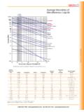
4 An easy to use programmable user interface with bright display offers precise control over water flow during ground water sampling events. Site-specific settings can easily be stored and recalled for repeatable efficiency during sampling events. Rugged construction and portability make connecting, installation and setup a breeze. The Controller also includes a user activated dry run protection feature. Pump Function and Theory Geotech 's SS Geosub Pump is a fully submersible environmental pump designed specifically for use in ground water sampling. All wetted parts are made from high quality inert materials so sample integrity is not affected during sampling. The SS Geosub flow rate can be adjusted to change from well purge flow rates to low flow sampling rates. Figure 1-1 contains a graph for the flow rates and operating depths. Drop Tube Intake System Geotech 's optional Drop Tube Intake System allows you to easily relocate the pump intake well beyond the depth limitations of the pump.
5 As long as the pump remains submerged, you can effectively and economically low flow a sample from a deeper point within the well's screened section. See Figure 2-1. 4. Figure 1-1: Pump Performance Chart Dry Run Feature Operation and Theory The Dry Run pump protection feature operates by measuring the output current level and comparing it to a user enterable set point. Many factors can influence the pump current draw, including head pressure, length of tubing and length of cable. Under all conditions, one thing remains the same: While pumping water, the pump draws higher current from the Controller than when it is out of water and running dry regardless of other variables. Dry Run is intended for use in situations where flow rates are above .1 GPM (.38 LPM). Results using Dry Run with lower flow rate are un-reliable. Pump Speed Control Operation and Theory Pump speed control is achieved by pressing the up or down button during run time. The number can be adjusted from 1 to 255 in increments of one unit.
6 The adjustments can be made one at a time by pressing the or button once or can be changed rapidly by holding the or button. This number is representative of power output. Most conditions do not allow for the full 1 to 255. point range of use. At the upper end of the scale, the Controller automatically prevents the user from overpowering a pump. The Controller indicates when max 5. power has been reached and prevents the user from increasing the output further. In most cases, the usable range of control will be a 100 point window somewhere within the 1 to 255 point range. In general, the longer the cable being used the higher the speed set point and vice versa. Other application specific conditions such as head pressure and tubing size will also affect the speed set point window of operation. When adjusting the speed at the lower end of the 1 to 255. point scale, the pump may shut down. This fault condition is most obvious when a system has high flow, low pressure and long cable.
7 PUMPING WELL. #nn nnn DR ON. OR. PUMPING WELL. #nn nnn DR OFF. Where #nn = Well #. nnn = Pump speed nn = Time to reset dry well in minutes DR = Dry Run setting (ON/OFF). 6. Section 2: System Installation READ BEFORE PROCEEDING ANY FURTHER. The SS Geosub Controller operates on high voltages supplied by a portable generator or grid-supplied main power. Care must be taken at all times to avoid electrical shock. Do not subject the SS Geosub Controller to contact with water. A grounding rod or stake driven directly into moist earth must be installed and electrically connected if using a portable generator larger than 2000 Watts. The SS Geosub Controller operation should be performed only by qualified persons. Reading this manual is essential for operating this equipment safely. If, after reading this manual, you are still unsure about the operation of this equipment contact Geotech for further information and training. The SS Geosub Controller stores energy for short periods even after power has been removed.
8 The SS Geosub Controller has no field serviceable components and should never be opened by an unqualified person. The SS Geosub Controller has been specifically designed for use with Geotech 's SS Geosub Pump ONLY! Care must be taken when operating any equipment that operates on main voltage. Contact Geotech for service or repair. (See Section 5, System Troubleshooting, for common fault conditions and suggestions on how to correct issues). Verify intended power source matches the model supply specifications of the SS Geosub Controller in use. SS Geosub Controllers are available in 120 VAC and 230 VAC 50/60HZ and models and must be powered accordingly. Damage will result if controllers are connected to incorrect input power supply. Once input power source has been verified, connect input power cable to the SS Geosub Controller , and then connect cable to power source, portable generator or main grid power. 7. Connect input power cable. The display will light up, and after a short startup sequence is executed, a message will display indicating the Controller status.
9 Attach the pump to the Controller using factory-installed connectors on both the SS Geosub Controller and pump cable. Use of any other connectors or method of attaching pump to Controller will cause shock and or fire hazard. When the status display shows Main Menu proceed to Section 3: System Operation. If display is blank, shows a fault or error condition, proceed to Section 5: System Trouble Shooting. Drop Tube Intake Assembly Installation and Operation The optional Drop Tube Intake Assembly is designed to allow you to relocate the SS Geosub Pump intake to a deeper screened part of the well. The SS Geosub Pump can either be built with a Drop Tube Intake and the necessary tubing length attached, or the Drop Tube Intake Assembly parts can be added to an existing pump at a later time. An example of all Drop Tube Intake parts can be found in Section 7: Replacement Parts List. When using a Drop Tube Intake with your SS Geosub Pump, the pump must be placed below the static water line, as shown in Figure 2-1.
10 Using a Drop Tube Intake can keep the pump at an optimum depth to maximize performance and the assembly is easily adaptable in the field. Drop Tube tubing lengths are custom to each well. When using or re-using poly tubing, it is suggested that small hose clamps be attached at the two hose barbs to prevent the accidental detachment of the drop tube assembly within the well. 8. Figure 2-1: SS Geosub Pump with Drop Tube Assembly in well 9. Section 3: System Operation Key Pad Description: This arrow is used to configure well option, raise the speed of the pump, and adjust settings in the program. This arrow is used to lower pump speed and adjust other settings of the program. This button will return you to the MAIN MENU from anywhere in the program. This button is used to start the pump, confirm selections and advance to the next section of the program. Basic Operation Plug power cord into Controller . Plug power cord into AC supply outlet. Wait for initialization sequence to complete.