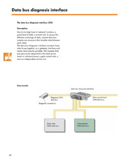
Transcription of SSP308 Direct Shift Gearbox 02E - VolksPage
1 DDDD irect SSSS hift GGGG earbox 02 ESelf- study programme 308 Service Training2 This self- study programme is designed to help you understand the Direct Shift Gearbox . There is also a multimedia CD available on the Direct Shift CD allows you to see how individual components work and how they combine with other components for operation of the interactive menus, the subjects Selector lever Gearbox construction Oil lubrication circuit Selection actuatorscan be This self- study programme shows the design and function of new developments!The contents will not be the latest testing, adjustment and repair instructions, please refer to the relevant service .. 4 Selector lever .. 6 Construction of DSG .. 12 Basic principle.. 12 Torque input .. 13 Multi-plate clutches .. 14 Input shafts .. 16 Output shafts .. 18 Reverse shaft .. 20 Differential .. 21 Parking lock .. 22 Synchronisation.. 23 Torque transmission in vehicle.
2 24 Transmission route through gears .. 25 Mechatronics module .. 28 Electro-hydraulic control unit .. 30 Oil lubrication circuit .. 32 System overview .. 40 Sensors/actuators ..42/50 Functional diagram .. 56 CAN data bus connection .. 58 Diagnosis .. 59 Service .. 60 Test yourself .. 614 IntroductionThanks to the double multi-plate clutch design and different automatic gear selection programmes, it is well capable of meeting the high demands in comfort from drivers who favour automatic , with Direct selection and lightning fast, jolt-free gear changes, it also offers a high level of driving enjoyment to drivers who favour manual both cases, fuel consumption is at a par with economical vehicles fitted with manual , the world of transmission is dominated in Europe by manual gearboxes and in the USA and Japan by automatic gearboxes. Both types of gearboxes have specific advantages and advantages of a manual Gearbox are, for example, high degree of efficiency robust and sporty advantages of an automatic Gearbox are, for example, a high level of comfort, above all in gear changes, as there is no interruption in tractive formed the framework for Volkswagen to combine both transmission concepts into one completely new Gearbox generation.
3 The Direct Shift pressure filterOil coolerMechatronicsMulti-plate clutchOil pump5 The Direct Shift Gearbox is distinguished by Six forward gears and one reverse gear Normal driving program "D",sports program "S" as well asTiptronic selector lever and Tiptronic steering wheel levers (optional) Mechatronics, electronic and electro-hydraulic control unit form one unit and are housed in the Gearbox Hillholder function if the vehicle begins to move when stationary, with just light brake application, the clutch pressure is increased and the vehicle is held in position Creep regulation allows creeping of the vehicle, when parking for example, without accelerator pedal application Emergency modeIn the event of a fault, the vehicle can still be driven, with emergency mode activated, in 1st and 3rdgear or just in 2nd 02E ( Direct Shift Gearbox )WeightApprox. 94 kg front-wheel drive, 109 kg 4motionTorqueMaximum 350 Nm (depending on engine)ClutchTwo multi-layer wet plate clutchesGear stagesSix forward, one reverse gear (all synchronised)Operating modeAutomatic and TiptronicOil ltr.
4 DSG oil G052 182 The Direct Shift Gearbox is already available for Golf R32 and Touran models. Future plans are to make it available for the New Beetle and Golf dataS308_003 Oil coolerOil pressure filterElectrical connection to vehicle6 OperationThe selector lever is actuated in the vehicle in the same way as an automatic Gearbox . The Direct Shift Gearbox also offers the option of Tiptronic gear in vehicles with automatic gearboxes, the selector lever features lever locks and an ignition key lock. The function of the locks remains unchanged. The design, however, is gear selector lever positions are:P - ParkTo move the selector lever out of this position, the ignition must be "on" and the brakes , the release button on the selector lever must be - Reverse gearTo engage reverse gear, the release button must be - Neutral position In this position, the Gearbox is at , for a length of time, the gear selector lever is left in this position, the brake pedal must be pressed for it to be - DriveIn this position, the forward gears are selected - Sport Gears are selected automatically using a "sporty" program stored in the control unit.
5 + and The Tiptronic functions can be used with the selector lever in the right gate and with the steering wheel gear leverRelease buttonS308_004S308_063 Steering wheel gear selectors7 Design of selector leverSelector lever sensors control unit J587 Hall sensors in the gear selector lever mounting detect the position of the selector lever and make the positions available to the mechatronics via the CAN bus .Selector lever lock solenoid N110 Solenoids hold the selector lever in positions "P" and "N". The solenoid is activated by the selector lever sensor control unit lever locked in position "P" switch F319If the selector lever is in the "P" position, selector lever locked in position "P" switch sends a signal to the steering column electronics control unit control unit requires this signal for actuation of the ignition key withdrawal N110 Locking pin hole "P"Locking pin hole "N"Hall sensors for detection of selector lever positionSelector lever sensors control unit J5878 Selector leverSelector lever locked in "N":If the selector lever is in the "N" position for longer than 2 seconds, the control unit will energise the solenoid.
6 In this way, the locking pin is pushed into the locking pin hole "N". The selector lever can no longer be moved inadvertently into a drive position. The locking pin is released when the brake pedal is lever lock solenoid N110 This is how it works:Selector lever locked in "P":When the selector lever is in the "P" position, the locking pin is in the locking pin hole for "P". This way, the selector lever is stopped from being moved inadvertently out of lever released:When the ignition is switched on and the brake pedal is pressed, the selector lever sensors control unit J587 energises the solenoid N110. In this way, the locking pin is pulled out of the locking pin hole "P".The selector lever can now be moved into the drive pin hole for "N"S308_103 Locking pin hole for "P"Locking pinSelector leverlock solenoid N110 Spring9 Emergency releaseIf the power supply fails to the selector lever lock solenoid N110, the selector lever can no longer be moved because selector lever lock "P" remains activated in the event of power pressing in the locking pin mechanically using a thin object, the lock can be released and the selector lever can be moved out of the "N" position for emergency vehicle can then be driven leverIgnition key withdrawal lockThe ignition key withdrawal lock prevents the ignition key from being turned to the withdrawal position unless the parking lock is works on an electro-mechanical principle and is actuated by the steering column electronics control unit is how it works.
7 Selector lever in "park position", ignition switched the selector lever is in the park position, the "selector lever locked in position P" F319 is steering column electronics control unit J527 detects the open switch. The ignition key withdrawal lock solenoid N376 is not supplied with spring in the solenoid pushes the locking pin to the release N376 Locking pinRetaining lug"Ignition off"S308_092aSpring11 This is how it works:"Selector lever in drive position", ignition the drive position, the "selector lever locked in position P" switch F319 is closed. The steering column electronics control unit then energises the ignition key withdrawal lock solenoid N376. The locking pin is pushed into the lock position against spring pressure by the the lock position, the locking pin prevents the ignition key from being turned back and until the selector lever is placed in the park position is the "selector lever locked in position P" switch opened.
8 The control unit then isolates the power supply to the locking pin is then pushed back by the spring. The ignition key can be turned further and "Ignition on"N37612 Construction of DSGB asic principleThe Direct Shift Gearbox comprises in essence of two transmission units that are independent of each other. Each transmission unit is constructed in the same way as a manual Gearbox . Allocated to each transmission unit is a multi-plate clutch. Both multi-plate clutches are of the wet type and work in DSG oil. They are regulated, opened and closed by the mechatronics system, depending on the gear to be , 3rd, 5th and reverse gear are selected via multi-plate clutch , 4th and 6th gear are selected via multi-plate clutch transmission unit is always in gear and the other transmission unit has the next gear selected in preparation but with the clutch still in the open gear is allocated a conventional manual Gearbox synchronisation and selector unit 2 Transmission unit 1 Engine torqueMulti-plate clutch K2 Multi-plate clutch K1 Diagram showing principle of operation13 Torque inputThe torque is transmitted from the crankshaft to the dual mass splines of the dual mass flywheel on the input hub of the double clutch transmit the torque to the drive plate of the multi-plate is joined to the outer plate carrier of clutch K1 with the main hub of the multi-plate outer plate carrier of clutch K2 is also positively joined to the main hubMain hubOuter plate carrier K1 Outer plate carrier K2 Dual massflywheelDrive plate14In this way.
9 Plunger 1 is pushed along its axis and the plates of clutch K1 are pressed together. Torque is transmitted via the plates of the inner plate carrier to input shaft the clutch opens, a diaphragm spring pushes plunger 1 back to its start clutch K1 Clutch K1 is of the multi-plate type. It is the outer clutch and transmits torque to input shaft 1 for 1st, 3rd, 5th and reverse close the clutch, oil is forced into the oil pressure chamber of clutch K1. Construction of DSGS308_039 Clutch K1 Plunger 1 Input shaft 1 Oil pressure chamber K1 Diaphragm springInner plate carrier K1 Outer plate carrier K1 Multi-plate clutchesThe torque is transmitted to the relevant clutch through the outer plate carrier. When the clutch closes, the torque is transmitted further to the inner plate carrier and then to the relevant input shaft. One multi-plate clutch is always clutch K2 Clutch K2 is of the multi-plate type. It is the inner clutch and transmits torque to input shaft 2 for 2nd, 4th and 6th close the clutch, oil is forced into the oil pressure chamber of clutch K2.
10 Plunger K2 then joins the drive via the plates to input shaft coil springs press plunger 2 back to its start position when the clutch is K2 Plunger 2 Oil pressure chamber K2 Inner plate carrier K2 Coil springInput shaft 216 Construction of DSGI nput shaftsThe engine torque is transmitted to the input shafts from multi-plate clutches K1 and shaft 2 Input shaft 1S308_010 Input shaft 2 Input shaft 2 is shown in relation to the installation position of input shaft gear2nd gearPulse wheelS308_084 Input shaft 2 is a hollow construction and is joined via splines to multi-plate clutch helical gear wheels for 6th, 4th and 2nd gear can be found on input shaft 6th and 4th gear, a common gear wheel is measure the speed of this input shaft there is a pulse wheel for input shaft 2 speed sender G502 adjacent to the gear wheel for 2nd shaft 1 Input shaft 1 rotates inside input shaft 2, which is hollow. It is joined to multi-plate clutch K1 via on input shaft 1 are the helical gear wheels for 5th gear, the common gear wheel for 1st and reverse gear and the gear wheel for 3rd measure the speed of this input shaft there is a pulse wheel for input shaft 1 speed sender G501 between the gear wheels for 1st/reverse gear and 3rd gear.