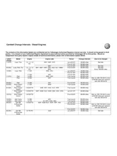
Transcription of SSP337 The 2.0l FSI engine with turbocharger
1 The FSI engine with turbochargerDesign and functionSelf-study programme 337 Service Training2 NEWW arningNoteThe self-study programme shows the designand function of new contents will not be instructions on testing, adjusting and repairs,please refer to the relevant service new FSI engines from Volkswagen do without stratified injection and place greater emphasis on output and torque. Until now, FSI direct injection was always associated with stratification. On the turbocharged engine , the abbreviation FSI remains but there is no stratified without fuel stratification and NOx sensors represents a loss on one part, but also promises the finest driving enjoyment with high output and a torquey engine and great pulling power and this self-study programme you can familiarize yourself with the technical highlights of this information can be found in self-study programme no. 322 - The FSI engine with 4-valve a glanceIntroduction .. 4 engine mechanics.
2 6 engine management .. 12 Service .. 24Te st yo u r k n ow l e d g e .. 264 Description of the engineIn terms of basic dimensions and design, the turbo FSI engine is derived from the FSI with engine code order to meet the high expectations of a turbocharged engine , components of the engine had to be adapted to specific exhaust manifold and the turbocharger form one unit. The exhaust and turbo module is customer service friendly and is attached to the cylinder head by a clamping crankshaft mechanics have been adapted to the higher demands of a turbocharged FSI manifoldTu r b o c h a rg e rS337_004Tu r b o c h a rg e r a i r recirculation valve N249 Solenoid valve forcharge pressurecontrolN75 PistonConrodCrankshaftResonance silencer5In order to meet the higher levels of power and heat transfer, the cylinder head has been adapted to the specific inlet camshaft features continuously variable valve timing (adjustment range 42 crankshaft angle).
3 S337_005 The optimised balancer shaft gear (AGW) is driven by a decoupled drive chain sprocket. The function is similar to that of a dual mass headInlet portsDecoupled drive chain sprocketBalancer shaft gear6 engine mechanicsTe c h n ical dataThe turbocharged FSI engine was first installed in the Audi A3 Sportback. At Volkswagen, the engine finds its debut in the Golf c h n i c a l fe a t u r es- turbocharger in exhaust manifold-Single pipe exhaust system with starter and underbody catalyst close to engine -Hitachi high pressure pump resistant to ethanol-Non-return fuel system-Homogenous fuel injectionS337_007Te c h n i c a l d a t aEngine codeAXXE ngine type4-cylinder in-line engineCapacity [mm3]1984 Bore [mm] [mm] :1 Max. output147 kW at 5700 rpmMax. torque280 Nm at 1800-4700 rpmEngine managementBosch Motronic MED r i a b l e v alve timing42 crankshaft angleExhaust gas recirculationInner exhaustgas recirculationFuel Premium unleaded RON 98 (normal unleaded RON 95 with reducedperformance)Exhaust gas treatment2 three-way catalytic converters with lambda controlEmissions standardEU 4To rq ue a n d p e r formance graphS337_008 Speed[rpm]To r q u e[Nm]Output[kW]7 The crankshaftThe component strength was adapted to the higher combustion contact faces of the main journals and conrod journals were made larger to improve strength.
4 engine blockThe cylinder contact surfaces of the cast iron engine block were honed by means of liquid blasting and smooth honing are an extension of the familiar two-stage honing technique by two additional process stages. In the first new processing stage, any compacting of the bushing contact surface brought about from the high pressure procedure is removed, and scores and damage from honing and cracks from alloying are rectified. The resulting surface is thereby largely free of metallic imperfections. In the final honing operation, the rough edges arising from blasting and any remaining rough areas are smoothed out to the highest level. This type of honing shortens the running-in time of the engine and leads to lower oil pistonsThe piston crown of the T-FSI has been adapted to the homogenous combustion 4V 4V T-FSI8 The balancer shaft gearThe balancer shaft gear was taken over from the common FSI engine . However, it had to be modified as follows: Decoupled drive chain sprocket in balancer shaft mechanism Separation of splines and compensation weights to increase balancing efficiency Oil pump with greater gear width Pressure relief valve, controlled purely by oil, with oil control in vicinity ofoil pump, integrated in balancer shaft housing Strength optimised pressure cast housing Bearings of balancer shaftslocated directly in aluminium housingEngine mechanicsThe decoupled drive chain sprocketThe improved smooth running of the crankshaft in the lower speed range leads to a considerable increase in chain forces in the balancer shaft gear.
5 with a relative crankshaft vibration angle of on the normal FSI engine , the increased crankshaft vibration angle of 2 on the turbocharged FSI engine is much more noticeable. Due to the increased load of the chain drive, the chain would be subjected to increased wear if there were no countermeasures. Therefore, there are curved springs in the hub of the chain sprocket. These decouple the input shaft of the balancer shaft gear to the crankshaft. S337_013 Diamond washerHubFriction bearingCurved springs (qty. 2)Friction washerDished washerEnd washerChain sprocketCrankshaftDrive chain sprocketDrive gearBalancer wheelsBalancer shaftsSuction lineOil pumpS337_012 Balancer shaft housing9 The toothed belt drive mechanismAs with all 4-cylinder in-line engines of series 113, the valve timing is designed as a toothed belt and direct exhaust camshaft drive to considerably higher demands on the toothed belt drive mechanism, such as: higher valve spring forces due to turbo turbo-specific timing in conjunction with adjustment range of 42 CA from continuously variable valve timing (inlet camshaft).
6 High pressure pump drive by means of3 cams on inlet camshaft,the toothed belt tensioning system, adopted from the naturally aspirated engine , was modified. This resulted in an elliptical toothed belt pulley on the CTC toothed belt pulley*, used for the first time, reduces rotational vibrations on the camshaft and pulling forces on the toothed belt. * CTC toothed belt pulley = Crankshaft Torsionals CancellationFunctionThe positioning of the toothed belt on the crankshaft is shown at TDC no. 1 cylinder, as in illustration 337_014. Once the working stroke begins, extremely high pulling forces are imparted on the toothed belt. These are reduced by the elliptical shape of the toothed belt pulley, due to the fact that the flat side of the pulley allows slight detensioning of the toothed belt. The rotational vibrations that arise as a result counteract the rotational vibrations of the 2nd engine order in the resonance point of the timing mechanism, without causing excessive unrest in other speed cylinder headTu r b o - s p e c ific changes were made to the cylinder head ( with regards to the FSI): Sodium filled exhaust valves Armoured inlet and exhaust valve seats Strength-optimised roller rocker fingers with reduction in web width from cams and rollers Va l v e s p r i n gs with increased spring forces (same valve springs for inlet and exhaust valves)Furthermore, the inlet port geometry was modified.
7 This enabled the tumble effect and thereby the knock resistance and smooth running properties to be 4V 4V T-FSIS337_01611 The crankcase breather systemThe constant vacuum in the crankcase is assured by a separate breather system for crankcase and cylinder blow-by gases emerging from the crankcase are passed via the primary oil separator in the oil filter module to the cylinder head this happens, the blow-by gases are mixed with those from the cylinder head and are passed through a labyrinth, where further oil separation turbo operation requires more complicated pressure control, there is a two-stage pressure relief valve on the cylinder head cover, which channels the blow-by gases to the intake manifold or turbocharger . When there is vacuum in the intake manifold, the blow-by gases are fed directly to the intake manifold. In the case of charge pressure, a non-return valve closes in the pressure relief valve housing. The blow-by gases are fed to the turbocharger via a channel in the cylinder head cover.
8 To recognize an incorrectly installed pressure relief valve, a so-called diagnosis port has been integrated. Incorrect installation forces unmetered air via the sealing area of the pressure relief valve into the cylinder head cover. The reaction of the lambda probe results in diagnosis of the unmetered air and a fault is then stored in the memory. S337_017 Labyrinth in cylinder head coverDiagnosischannelPressure reliefvalveNon-return locking valveGas outlet to turbochargerOil filter moduleGas outlet to intake manifoldWith charge pressure before turbochargerWith vacuum to intake manifoldNon-return locking valvePrimary oil separator12 engine managementS337_018 The turbocharger /exhaust manifold moduleTo s a v e s p a c e , an exhaust manifold/ turbocharger housing was developed, which can be installed with all engine variations in longitudinal or transverse configuration. Importance was also placed on realising a customer service orientated solution to allow the exhaust manifold to be removed and installed easily, and for a catalytic converter to be included close to the bearing of the turbine shaft is integrated in the compressor housing.
9 The cylinder head cover houses the crankcase and active charcoal breather connections. Screwed into the pressure connection is an individually tuned resonance silencer to reduce the pressure pulsation required charge pressure is adjusted via the charge pressure control solenoid valve N75 (pressure relief control as on l turbocharged engine ) and the so-called charge pressure control solenoid valve N75 and the turbocharger air recirculation valve N249 can be found on the breather connectionCoolant flow to radiator and from auxiliary water pumpActive charcoal filter connectionPressurised oil supplyTu r b o c h a rger air recirculation valve N249 Coolant supply to engine blockOil return13S337_019 The turbocharger with new flange fixtureThe turbocharger module is easy to fit and is attached to the cylinder head by five threaded connections. For removal and installation, the clamping strip need not be exhaust manifold is designed to take advantage of the firing order.
10 The manifold is fluted to channel the exhaust gases equally over the turbine. In this way, the exhaust ports are separated in line with the firing order. Furthermore, the flute channel prevents the exhaust gas pressure from expanding into other cylinder means that the required turbine speed is maintained and the response of the turbocharger could be stripFlute channel14 Control pressure is formed from the charge pressure and intake pressure via the energised charge pressure control solenoid valve N75. The control pressure affects the vacuum unit, which actuates the wastegate valve via a linkage. The wastegate valve opens a bypass channel to allow part of the exhaust gases past the turbine into the exhaust gas system. This control feature allows the speed of the turbine to be controlled and the maximum charge pressure can thereby be managementS337_020Tu r b o c h a rger air recirculation valve N249 Charge pressure control solenoid valve N75Va c u u m unitWa s t e g a t eCharge air coolerIf the control features fails, the vacuum unit is affected directly by the charge pressure, which imparts pressure against the spring.