Transcription of ST5484E Seismic Velocity 4-20mA Transmitter
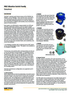
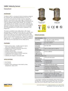
1 Doc# 1004457 ST5484E June 2018-Rev AH Page 1 of 9 ST5484E Seismic Velocity 4-20 mA TransmitterDatasheet2-Pin MIL Connector(Option D=4)The ST5484E is a self-contained Seismic Velocity Transmitter that incorporates a piezoelectric accelerometer, signal integrator, RMS peak detector, and a 4-20 mA signal conditioner into a single package. It can be mounted directly on a machine case or bearing housing without intervening signal conditioning equipment. The amplitude of the integrated acceleration ( Velocity ) signal is con-verted to a proportional 4-20 mA signal compatible with industrial process control instrumentation such as PLCs, DCSs, and SCADA systems that can provide trending and/or alarming capabilities for a simplified vibration monitoring the flying lead or terminal block connector options are chosen, the Transmitter does not need a separate environmental housing and can directly accept conduit.
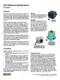
2 To reduce installed cost, it can be used with barriers for intrinsically safe installations, or wired directly to explosion-proof conduit fittings for explosion- proof A Local Display?When continuous, local indication of vibra-tion levels is required at the Transmitter , the Metrix ST5491E provides these capabilities. Its sensing and Transmitter elements are similar to the ST5484E , but it includes a convenient 2 digit LCD display in an integral conduit elbow and is rated for use in temperatures from -10oC to +70oC. Refer to Metrix datasheet 1004598 for ordering information and de-tailed vibration Transmitter may be appropriate in applications where a stand-alone monitoring system may not be ST5484E handles general-purpose vibration measurements on a wide range of rotating and reciprocating machinery with ro-tative speeds between 120- and 6,000-rpm.
3 Seismic measure-ments are suitable for machines with rolling-element bearings because shaft vibration in such machines is usually transmitted directly through the bearing to the bearing housing without sub-stantial damping or attenuation. Seismic transducers can also measure vibration that does not originate at the shaft, such as bearing-related wear and defects, footing/foundation problems, piping resonances that are coupled to the machine, Measure Velocity ?Acceleration and displacement levels are heavily influenced by the frequencies at which the vibration is occurring, while Velocity levels are much less influenced. Thus, although acceleration, Velocity , and displacement measurements are inter-related mathematically, Seismic Velocity measurements tend to be more consistent over a wide range of frequencies than either displace-ment or acceleration.
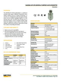
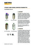
4 Consequently, broadband (sometimes called overall or unfiltered ) Velocity measurements are ap-propriate for monitoring many machines as a reliable indicator of damaging vibratory energy, with the notable exception of machines with fluid-film bearings, which are usually better ad-dressed by shaft-observing proximity displacement is not a practical measurement to make directly and is typically just an integrated Seismic Velocity mea-surement. As such, the primary decision when selecting a seis-mic sensor will usually be whether to measure casing Velocity or casing acceleration. As noted above, casing Velocity will often be more appropriate because it tends to be a more reliable indicator of damaging vibratory energy over a broad frequency spectrum for low- to medium-speed Leads(Option D=0, 1, 5, or 6) (2-wire shown; 4-wire also available)2-Pin Terminal Block(Option D=2)4-Pin Terminal Block(Option D=3) Doc# 1004457 ST5484E June 2018-Rev AH Page 2 of 9 ST5484E Seismic Velocity 4-20 mA TransmitterDatasheetNOTE: For machines with fluid-film bearings, shaft- observing proximity probes will provide more effective vibration measurements than Seismic transducers due to the rotor dynamics of the machine and the attenuation of vibratory energy through a fluid-film boundary.
5 Accord-ingly, Metrix recommends and provides proximity probes and associated 4-20 mA transmitters or monitoring systems for such machines with rolling element bearings and running above 6,000 rpm, and/or where impulsive casing vibration occurs, acceleration may be a better measurement. In such situations, it is recommended that you consult witha Metrix sales professional who can review your application and assist with selection of the proper transducer type and associated Transmitter or monitoring system. RFI/EMI Immunity Enhanced circuit design and installa-tion techniques aggressively filter out noise from common sources such as handheld radios Excellent Moisture Resistance The 2-pin MIL connec-tor version is hermetically sealed to provide an IP67-rated enclosure. Flying lead and terminal block versions are fully potted and rated to IP66 when installed with optional IEC conduit elbow Hazardous Area Approvals North American (CSA), Brazil-ian (INMETRO), and European (ATEX & IEC) approvals avail-able Dynamic Signal Availability 2-wire versions provide a 4-20 mA Velocity - proportional signal for easy connection to PLCs, DCSs, and other plant control systems.
6 Optional 4-wire ver-sions1 also provide the raw acceleration signal (100 mV/g) for use with vibration data collectors and analyzers Variety of Connection Options Flying leads, terminal block, and MIL-type connectors available Conduit-Ready2 Terminal block and flying lead options have conduit threads on top of sensor. No special housings are required for connection of conduit Rugged, Industrial Design Robust construction offers out-standing durability; built-in base and housing strain protec-tion helps ensure that over-torqueing sensor-to- machine and sensor-to-conduit connections won t damage internals or body High- and Low-Pass Filter Options The ST5484E can be ordered with a wide variety of low- and high-pass filter options to precisely tailor the band over which vibration is measured Polarity-Independent Wiring Metrix patented IPT tech-nology allows loop power to be connected without regard to voltage polarity, reducing field wiring errors and ensuring that the raw acceleration output1 is not phase inverted Multiple Mounting Options Integral and removable mounting stud options available in both metric and English thread sizes.
7 Flat base mounting adapters are also available Loop-Powered Runs on nominal 24 VDC power supplied by the 4-20 mA current loop Wide Supply Voltage Range Accepts loop power voltages from 11 to VDC (intrinsically safe) or VDC (explosion proof & non-incendive) RMS Amplitude Detection Measures Root Mean Square (RMS) vibration amplitude. Options available for True RMS or scaled RMS (RMS x 2) for derived peak Numerous Full Scale Ranges The full scale ranges provid-ed in option AAA reflect frequently-ordered ranges; how-ever, many others (too numerous to list) are also available. Consult factory for applications requiring other full scale rangesNotes:1. Dynamic raw acceleration signal available with 4-wire versions only (ordering options D= 1 and D=3).2. Metrix recommends flexible (rather than solid) conduit when pos-sible. Solid conduit can introduce preload forces on the sensor and alter of the vibration response of the Voltage(see also note under max loop resistance)11 VDC (24 VDC nominal) (intrinsi-cally safe); 11 30 VDC (24 VDC nominal) (explosion proof and non-incendive);Metrix patented IPT independent polar-ity diode bridge circuit allows voltage to be connected without regard to polarityCircuit-to-Case Isolation500 VrmsOutputs4-20 mAProportional to Velocity full scalerange (4mA = 0 vibration, 20mA = full scale vibration)Maximum 4-20 mA loop resis-tanceRL = 50 x (Vs 11) W where Vs = Supply Voltage at Transmitter : For every 50 W of resistance in the 4-20 mA loop, 1 VDC above the minimum sup-ply voltage (11 VDC) must be available at the Transmitter terminals.
8 For example, 12 VDC at the Transmitter terminals will allow a 50 loop resistance; 30 VDC at the Transmitter terminals will allow a 950 loop resistance. For intrinsi-cally safe applications, the use of a passive zener barrier will incur a voltage drop of approximately volts at the barrier, and the loop supply voltage is limited to 26 VDC. Thus, with passive barriers and a 26 VDC supply, the maximum available voltage at the Transmitter will be VDC and the corresponding maxi-mum loop resistance will be 345 .Dynamic Signal100 mV/g ( mV / m/s2) acceleration, filtered to same frequency band as pro-portional Velocity (see ordering options E & F)All specifications are at +25 C (+77 F) and +24 VDC supply voltage unless otherwise Doc# 1004457 ST5484E June 2018-Rev AH Page 3 of 9 ST5484E Seismic Velocity 4-20 mA TransmitterDatasheetDynamic Signal Output Impedance 10 k NOTES:1.
9 The dynamic signal output is short-circuit protected by means of a 10 k resistor, resulting in a relatively large output imped-ance. Many data collectors and analyzers have relatively low input impedances (100 k or less) which will load this dynamic output and attenuate the signal by 10% or more. Refer to Table 1 for the dB and percentage attenuation for various load Because the ST5484E is a loop-powered device with low operating power, the dynamic signal output requires a buffer amplifier for ca-ble runs in excess of 16 feet (5 meters). Longer cable runs will also introduce distributed cable capacitance that acts as a low-pass filter, attenu-ating high- frequency signal content. In such situations, consult the factory for assistance selecting an appropriate low-capacitance Load Imped-ance (Zload) for Dynamic Signal Connection500 k (see also note 1 above)Signal ProcessingFrequencyResponse (+/-3dB passband)2 Hz 1500 Hz (standard)2 Hz 2000 Hz (optional)Optional High- Pass Filter Corner5, 10, 20, 50, 100, or 200 Hz (must be specified at time of ordering)High-Pass Roll-Off12 dB / octaveOptional Low-Pass Filter Corner230, 250, 350, 450, 500, or 1000 Hz(must be specified at time of ordering)Low-pass Roll-Off12 dB / octaveAccuracy (within passband) 4% (at corner frequencies)Maximum Full in / sec (others by request)Minimum Full in / sec (others by request)Full Scale Range Units in / sec (standard) mm / sec (available by request)Amplitude DetectionTrue RMS detector.
10 Full scale may be or-dered with True RMS units or scaled RMS (RMS x 2) for derived peak measure-mentsSee ordering option Temperature-40 C to +100 C (-40 F to +212 F) lbs ( kg)DimensionsRefer to Figures 1 and 2 on page 8 Sensitive AxisSame as mounting stud axisAxis OrientationAnyEnclosureMaterial 303 stainless steel (standard) 316 stainless steel (optional)Enclosure RatingMIL-Style Connector (option D=4): IP67 and NEMA 4 XFlying Leads and Terminal Block Connec-tors (option D 4): IP66 when used with the following con-duit elbows: 8200-001-IEC, 8200-003-IEC, 8200-008-IEC, No Rating* when used with the follow-ing conduit elbows: 8200-001, 8200-003, 8200-005, 8200-008, 8200-101, 8200-103, 8200-108* NOTE: IP and NEMA ratings pending; refer to table on page Types Flying Leads (2- and 4-wire) MIL-C-5015 (2-wire only) Terminal Block (2- and 4-wire)Humidity 95%, non-condensing (flying lead and terminal block versions) 100% condensing (MIL-style connector)ApprovalsCE Mark YesHazardousAreas CSA ATEX IECEx INMETRO KOSHA Custom Union EACR ecommended IS BarriersPassive (ZenerType)MTL 7787+ or equalActive (Zener Type)MTL 7706 or equalActive(Galvanic Type)MTL 5541 or equalST5484E Entity Parameters Vmax: VDC (intrinsically safe) Vmax: 30 VDC (explosion proof and non-incendive) Imax.