Transcription of Standard Specification for Cast Iron Couplings …
1 Designation: A 1056 08 Standard Specification forCast iron Couplings Used for Joining Hubless cast iron SoilPipe and Fittings1 This Standard is issued under the fixed designation A 1056; the number immediately following the designation indicates the year oforiginal adoption or, in the case of revision, the year of last revision. A number in parentheses indicates the year of last reapproval. Asuperscript epsilon ( ) indicates an editorial change since the last revision or This specification covers the materials and testing ofcast iron Couplings for joining hubless cast iron soil pipe andfittings for sizes 11 2to 10 It is the purpose of this specification to furnish informa-tion as to the characteristics of a particular sleeve type couplingwhen applied to cast iron soil pipe and fittings manufactured inaccordance with SpecificationA 888, latest revision, and CISPID esignation 301, latest The values stated in inch-pound units are to be regardedas Standard .
2 The values given in parentheses are mathematicalconversions to SI units that are provided for information onlyand are not considered The following precautionary caveat pertains only to thetest method portion, Section8, of this does not purport to address all of the safety concerns,if any, associated with its use. It is the responsibility of the userof this Standard to establish appropriate safety and healthpractices and determine the applicability of regulatory limita-tions prior to Referenced standards :2A 48/A 48 MSpecification for Gray iron CastingsA 644 Terminology Relating to iron CastingsA 888 Specification for Hubless cast iron Soil pipe andFittings for Sanitary and Storm Drain, Waste, and VentPiping ApplicationsC 564 Specification for Rubber Gaskets for cast iron SoilPipe and FittingsD 2240 Test Method for Rubber Property DurometerHardnessE8 Test Methods for Tension Testing of Metallic standards :3 ANSI and Hex Bolt and Screws Inch SeriesANSI and Hex Nuts (Inch Series) Standard .
3 4 CISPI-301 Specification for Hubless cast iron Soil pipe andFittings for Sanitary and Storm Drain, Waste and VentPiping Applications3. Definitions of the following terms used in this speci-fication are found in TerminologyA 644: elastomeric, durom-eter and of Terms Specific to This stop,n an integral part of the gasket centeredon the axial length of the gasket intended to limit the insertiondepth of the pipe and/or fitting to be assembly,n that portion of the couplingexcluding the gasket, nuts and ,n the complete ,n parts of a pipeline other than straight pipes,valves, or ,n the elastomeric portion of the ,n the point of assembly consisting of thecoupling and the joined pipes or fittings, or of the clamp assembly,n the entitythat casts the clamp of the coupling .
4 N the entity that as-sembles the components of the coupling such as the gasket andthe clamp of the gasket,n the entity that pro-duces the elastomeric portion of the specification is under the jurisdiction of ASTM Committee A04 on IronCastings and is the direct responsibility of Subcommittee on Gaskets andCoupling for Plumbing and Sewer edition approved June 1, 2008. Published June referenced ASTM standards , visit the ASTM website, , orcontact ASTM Customer Service at ForAnnual Book of ASTMS tandardsvolume information, refer to the Standard s Document Summary page onthe ASTM from American National standards Institute (ANSI), 25 W.
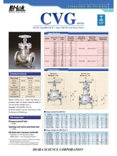
5 43rd St.,4th Floor, New York, NY 10036, from cast iron Soil pipe Institute (CISPI), 5959 Shallowford Rd.,Suite 419, Chattanooga, TN 37421, ASTM International, 100 Barr Harbor Drive, PO Box C700, West Conshohocken, PA 19428-2959, United Materials and Physical properties of gaskets shall comply with Speci-ficationC 564and the dimensions, material specifications,physical and chemical properties as shown inFig. 1,Fig. 2,Table 1, andTable All cast iron parts shall be made of a minimum class 25cast iron and shall show compliance to this requirement usingtest methods contained in SpecificationA 48/A in.
6 (mm)11 2( )2 ( )3 ( )4 ( )5 ( )6 ( )8 ( )10 ( ) ( ) ( ) ( ) ( ) ( ) ( ) ( ) ( ) ( ) ( ) ( ) ( ) ( ) ( ) ( ) ( ) ( ) ( ) ( ) ( ) ( ) ( ) ( ) ( ) ( ) ( ) ( ) ( ) ( ) ( ) ( ) ( ) ( ) ( ) ( ) ( ) ( ) ( ) ( ) ( ) ( ) ( ) ( ) ( ) ( ) ( ) ( ) ( ) ( ) ( ) ( ) ( ) ( ) ( ) ( ) ( ) ( ) ( ) ( ) ( ) ( ) ( ) ( ) ( ) ( ) ( ) ( ) ( ) ( ) ( ) ( ) ( )NOTE Dimensional Tolerances to be RMA Class 3 (seeTable 1).FIG. 1 Rubber GasketA1056 The manufacturer of the clamp assembly shall per-form tests to determine mechanical properties of the iron usedin the manufacture of iron soil Couplings . Tension test speci-mens shall be employed.
7 The manufacturer of the clampassembly shall maintain a record of mechanical tests for aminimum of 7 Strength Test Test bars shall be cast inaccordance with the requirements of SpecificationA 48/A 48M. The machined test bar dimensions and drawing anddimensions of as cast test bars are found in Fig. 1 of Specifi-cationA 888. The tensile strength shall be determined inaccordance with Test MethodsE8. The tensile strength shall benot less than 25 000 psi (145 MPa). Tension test reports shall include breaking load of testbars, machined diameter of test bar, and calculated Analysis of castings or test bars after the time ofproduction shall not be used as evidence of compliance to Nuts and bolts shall be stainless steel Grade 304, shallconform to the requirements of ANSI Specification , and shall not have screwdriver Elastomeric Gasket The elastomeric gasket shall consist of one piece con-forming to the physical requirements of SpecificationC 564with hardness (nominal durometer65)
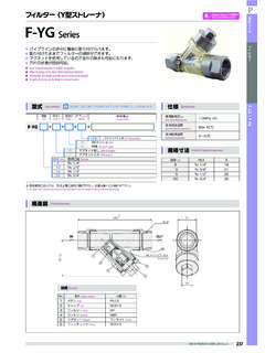
8 70 as tested inaccordance with SpecificationD The elastomeric gasket shall have an inside center stopthat does not create an enlargement chamber or recess with aledge, shoulder, or reduction of pipe area or offer an obstruc-tion to The elastomeric gasket shall be free of defects thataffect the use and Clamp Assembly The clamp assembly material shall be class 25 cast ironand comply this The clamp assembly shall comply with dimensionspecifications, as are given inFig. 2,Fig. 3, andFig. 4. Theclamp assembly shall consist of two sections that interlockusing a nut and bolt. The clamp assembly shall have theminimum wall thickness along the ring wall and the minimumwall thickness along the ear wall with tapered ends as shownonFig.
9 Clamp assemblies shall be tested to withstand no lessthan 125 % of manufacturer of the coupling s stated installa-tion torque or a minimum of 175 lbf in. ( N m) of appliedtorque, whichever is greater, without visible signs of clamp assembly shall be tested over a steel mandrel of theappropriate diameter and torqued as The clamp assembly shall be designed to accommo-date maximum and minimum OD s of pipe and fittings asshown inTable The manufacturer of the coupling shall, upon receipt ofa shipment of clamp assemblies from the manufacturer of theclamp assemblies, take a random sampling of couplingsNominal Size in.
10 (mm) coupling Size in. (mm)Bolt Size in. (mm) coupling SizePipe DiameterHeight XWidth YDepth 2(38) ( ) ( ) ( ) ( ) (50) ( ) ( ) ( ) ( ) (76) ( ) ( )6 ( ) ( ) (101) +.09 ( + ) ( )7 ( ) ( ) (127) +.09 ( + )6 .25 ( ) ( ) ( ) (152) +.09 ( + ) ( ) ( ) ( ) (203) +.09 ( + ) ( ) ( )4 ( ) (254) ( ) ( ) ( )4 ( ) Tolerance shall in. ( ) unless otherwise 2 Clamp Assembly DimensionsTABLE 1 Dimensional Tolerances for Rubber StandardDimensional Tolerances RMA CLASS 3 NOTE and over multiplied by These are in. (mm)Fixed,6in. (mm)Closure,6(in.)