Transcription of Standard Thermoforming Equipment Overview - …
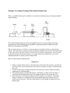
1 Standard Thermoforming Equipment Overview There are three Standard configurations for Thermoforming Equipment : 1. Heat and Cut-in-Place Forming 2. In-Line Forming with Steel Rule or Forged Steel Trim wand Air Pressure and/or Plug Assist 3. Two Station Forming with Air Pressure and/or Plug Assist and Secondary Matched Metal or Forged Steel Trim In this section, each of these types will be considered from the perspective of Thermoforming polyester rollstock. An Overview of the technology will be offered, followed by a quick look at the advantages and disadvantages of that Equipment for processing PET.
2 1) Cut-in Place Thermoforming Process With this technology, the forming and cutting are accomplished in a single station, and the desired geometry is accomplished without the benefit of a mechanical plug assist. This can be accomplished because the mold is mounted to an upper platen, inside of the perimeter of the forged steel die, directly above the lower heated platen. The process begins by first holding the sheet against the heated platen by means of air pressure introduced through the mold, or vacuum introduced through the heated platen, after the leading edge of the forged steel cutting die engages the surface of the plastic.
3 This contact provides the seal needed for the next step in the forming process. Now air pressure, usually introduced through the heated platen, pushes the heated plastic into the mold geometry mounted inside the perimeter of the forged steel die. After cooling, the forged steel die is pushed the rest of the way through the plastic, into contact with the platen, and the part is cut. The part is ejected from the mold by means of air pressure, spring assisted ejection rings, or both. It is then conveyed to the next station inside the web.
4 This is facilitated by tiny precise notches in the cutting edge of the die. These notches hold the plastic in the web while being conveyed, but are kept small enough so the parts can be easily separated from the web for packing or filling. A simplified cut-in-place process description would look like this: 1. The plastic is pulled from the roll by index arm bars at the front of the machine, just above the roll stand and indexed into the heat/form/cut station. 2. The bottom platen strokes up as the top platen strokes down 3.
5 The leading edge of the forged steel cutting die engages the surface of the sheet and penetrates far enough to create a perimeter seal. 4. Air pressure is introduced through the mold, or in some cases vacuum introduced through the lower platen, holds the plastic against the heated lower platen. 5. The heated plastic is pushed off the lower platen upward into the mold on the platen above. 6. Once cool enough to maintain the desired geometry, the part is cut as forged steel die is brought into contact with the lower platen.
6 7. Both platens retract and the part is ejected from the mold with air or mechanical assistance or both. 8. The machine indexes and conveys the formed parts to the packing station. 9. Parts are removed from the web manually or mechanically. 10. The web is conveyed to a coreless winder that rolls the web into bales for recycling. Simplified Drawing of a Cut-in-Place Thermoformer Advantages The cut-in-place technology available today has several advantages. This type of Equipment generally produces the least amount of trim waste.
7 This is primarily because the cutting die not only cuts the part perimeter, but is also used to form the airtight perimeter seal needed to form the plastic. Another advantage is that the plastic is generally warm when it is trimmed. This is highly desirable when cutting PET because warm plastic requires dramatically less pressure to trim. These lower pressures usually extend the usefulness of the cutting edge of the die significantly. An additional advantage is in accuracy of trimming the part geometry.
8 Today s modern contact heat formers are achieving trim accuracy that approaches the precision found in match metal trim stations, at a significant cost savings. Finally, some plastics allow for extremely fast cycle times in parts of all geometries in shallow draft , shallow draw applications. Disadvantages The Cut-in Place Thermoforming machine is not optimal if the end use of the PET parts made with this process requires cold temperature resistance to fracture failure. Parts produced using this technology tends to exhibit higher percentages of residual stress when examined using polarized light.
9 Birefringence reveals this stress in clear PET parts and is observed as prismatic rainbows of color. These rainbows reveal where the stress is in the clear PET part. The likelihood of fracture failure is much greater in the highly stressed areas of these parts. Birefringence is caused when the light passing through the plastic splits, bends, or changes direction. When not all the stress can be eliminated, the process should then be adjusted to balance the observable stress. Parts that have unbalanced stress can also experience a significantly higher incidence of fracture failure than parts that exhibit low or balanced stress, at any temperature.
10 The incidence of residual stress in contact heat Thermoforming are usually attributable to the inability to heat both sides of the sheet equally, or to a limited number of temperature zones in the heated lower platen. 2) In-Line Thermoforming with Steel Rule or Forged Steel Trim with Vacuum, Air Pressure and Plug Assist This is a simplified drawing of an in-line Thermoforming machine: In-Line Process Overview With this type of machinery, the forming and cutting are accomplished in a two separate dual platen stations.