Transcription of Standard Welding Procedure for ExELL P20M Mold Steel …
1 ELLWOOD SPECIALTY Steel CO. 499 HONEYBEE LANE NEW CASTLE, PA 16105 PH: 800-932-2188 Fax: 724-654-9550 Standard Welding Procedure for ExELL P20M Mold Steel ExELL P20M High Hard ExELL P20M Lens Quality Introduction Tools and mold parts are welded for various reasons. Some of these reasons include: - Design changes - Correction of machining errors in tool making - Repair of cracked or worn tooling tool steels are generally considered to exhibit poor weldability due to the deep hardening and chemistry of these grades. Weld deposits cool quickly when the heat source is removed and the weld metal and surrounding heat affected zone will harden. Stresses from this hardening transformation are normally high and risk of cracking is possible.
2 However, tools and molds made from ExELL P20M and similar alloy types exhibit good weldability because of lower carbon and alloy contents. Because of the inherent general risk of cracking and the potential need for color match of a polished or textured finish on a critical molding surface application, care must be exercised during Welding of any tool . Successful weld repair is more likely if a suitable Procedure is adapted to the Steel grade. A Welding Procedure should include: - Preheat temperature for specific Steel grade during Welding - Maximum interpass temperature - Maximum cooling rate after Welding - Thermal treatment after cooling - Use of recommended filler metal consumable - Build up sequence of the weld Welding Methods TIG Welding TIG Welding can be performed using a regular SMAW power source provided this source is equipped with a TIG control unit.
3 The TIG unit should be water cooled and capable of handling a minimum current of 250 A at 100% intermittence. A foot pedal to step current adjustment from zero to optimum level will facilitate the Welding process. It is highly recommended for a gas lens to be utilized in the TIG unit to maximize inert gas protection. Gas flow must not be too low or too high. A gas flow of 17 27 cu. ft / hr. or 8 10 liters /min. is recommended. ARC Welding (Shielded Metal Arc Welding SMAW) An AC or DC power source can be used for SMAW provided the voltage and current capability is compatible with stick electrodes requirements. Basic coated electrodes of normal recovery are recommended.
4 A suitable power source for these electrodes is a DC unit with an open voltage of 70V and a capability of delivering 250A/30V at 355 intermittence. FILLER METAL CONSUMABLES Welding procedures should always incorporate requirements to facilitate or make Welding as easy as possible. Higher quality consumables should always be used to develop uniform composition, hardness, and freedom from non-metallic inclusions and porosity. In non-critical tool or part areas where higher hardness is not required or for filling of more massive weld build-up, use of nickel stainless (lower strength, high ductility) filler metal is suggested. In critical areas, filler metal for weld repair or at least the last number of runs should approximate the chemical composition and hardness of the base metal.
5 Appropriate high quality consumables for ExELL P20 Modified are available from manufacturers such as Weld Mold Co. and local Welding supply distributors. Specify a chemistry match to ExELL P20 Modified and required weld hardness level. Weld deposits should not be flame hardened. For weld repair of any flame hardened surface, use filler metal in the final 3 5 runs of hardness comparable to the flame hardening response of the base metal. In critical areas, the important weld metal properties include hardness, polishability, and texturing ability. Thus, use of high quality consumables with similar chemistry and/or hardness to the base metal is always recommended. Be sure the tool or part user has no special requirements or recommendations for weld repair filler metal.
6 NOTE: for small repairs and for at least the initial and final runs of larger repairs, the TIG Welding method is generally preferred for tool weld repair. TIG wire must be cleaned (light emery) prior to Welding and it is a good practice to end snip the wire between weld runs. SMAW coated electrodes are strongly hygroscopic and should only come in contact with dry air. Opened packs of electrodes should be stored in a drying cabinet at 120 300 degrees F. If electrodes are not absolutely dry, the weld will be contaminated with hydrogen. SURFACE PREPARATION In the vicinity of Welding , clean the metal surface with degreasing material and grinding before Welding .
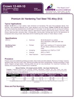
7 Area of weld repair must be cleaned to base metal. Protect surrounding area from spatter during Welding . Any cracks should be ground out so that the joint bottom is rounded to a width of about 1/16 inch greater than the wire diameter to be used. The sides of any joint preparation should angle at least 12 degrees to the vertical. NO NO YES YES For even very minor weld repairs, weld preparation must allow for at least two weld runs. The final weld run for any Welding should always be ground away after Welding . Welding Procedure Preheating For weld repairs of ExELL P20M, HH, or Lens Quality it is recommended to preheat to approximately 450-500 degrees F.
8 Preheating can be achieved through the use of a torch, furnace, heating elements or other appropriate means. Insulated boxes or thermal blankets can aid to maintain or better control the preheat operation. Small weld repairs of ExELL P20M generally do not require preheating. With good practice and technique these small repairs can be performed at room temperature. Weld Buildup Joint surfaces are generally clad in using TIG and several runs. In addition to maintaining a clean, non-porous, and gas free weld, control of temperature is also very critical during Welding especially with the initial and final runs of weld repair. To attain minimum heat input, a current of 110-120A should be used on these cladding in layers with a 1/16 inch wire.
9 Avoid excessively low currents which promote slow Welding speeds and high heat input. The arc should be struck in the joint and the sore from the arc striking should be melted up at the beginning of Welding . During Welding , the arc should be short and the beads deposited should tend to be flat and in distinct runs (for any Welding , runs must be limited to about 2 inches in length). The wire should be angled at 90 degrees to the joint sides to minimize undercut. The wire should also be held at an angle of about 75 degrees to the direction of forward movement. The initial layer should extend out of the weld joint on the base metal surface about 1/8 inch. Heat from subsequent runs will be utilized to temper the heat affect of the previous run s deposit.
10 Weld Buildup (Cont.) Between runs, clean deposit with a wire brush and inspect weld. Grind and correct problems such as undercut, inadequate melting, etc. Throughout Welding , limit maximum interpass temperature to 890 degrees F. A second weld layer is made with the same wire size and current to accommodate low heat input and to ensure minimal heat affected zone. This second run will extend somewhat less on the base metal surface than the first run. The remainder of the joint body can be welded with somewhat higher current if desired. Use heat from each run to temper the previous run. These runs should finish about 1/8 inch below the surface of the base metal.