Transcription of Star-Delta Transformer Connection Overview - IDC-Online
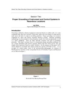
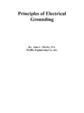
1 Electric power Transformer nameplate (50 MVA Substation Power Transformer with Load Tap Changer)Figure 1 - Transformer Connection - star -DeltajiguparmarStar- delta Transformer Connection OverviewStar- delta Connection OverviewIn this type of Transformer Connection , then primary is connected in star fashion while the secondary is connectedin delta fashion as shown in the Figure 1 voltages on primary and secondary sides can berepresented on the phasor diagram as shown in theFigure 2 points1. As Primary in star connected2. Line voltage on Primary side = 3 X Phase voltageon Primary side. So3. Phase voltage on Primary side = Line voltage onPrimary side / 34. Now Transformation Ration (K) = Secondary PhaseVoltage / Primary Phase Voltage5.
2 Secondary Phase Voltage = K X Primary PhaseFigure 3 - Y-D grounding transformerFigure 2 - Phasor diagram with voltages on primary and secondary As Secondary in delta connected:7. Line voltage on Secondary side = Phasevoltage on Secondary Secondary Phase Voltage = K X PrimaryPhase Voltage. =K X (Line voltage onPrimary side / 3)9. Secondary Phase Voltage = (K/ 3 ) XLine voltage on Primary There is s +30 Degree or -30 DegreePhase Shift between Secondary PhaseVoltage to Primary Phase VoltageAdvantages of star DeltaConnection1. The primary side is star connected. Hence fewer numbers of turns are required. This makes the connectioneconomical for large high voltage step down power The neutral available on the primary can be earthed to avoid The neutral point allows both types of loads (single phase or three phases) to be Large unbalanced loads can be handled The Y-D Connection has no problem with third harmonic components due to circulating currents inD.
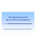
3 It isalso more stable to unbalanced loads since the D partially redistributes any imbalance that The delta connected winding carries third harmonic current due to which potential of neutral point isstabilized. Some saving in cost of insulation is achieved if HV side is star connected. But in practice the HVside is normally connected in delta so that the three phase loads like motors and single phase loads likelighting loads can be supplied by LV side using three phase four wire As grounding Transformer : In Power System Mostly grounded Y- Transformer is used for no otherpurpose than to provide a good ground source in ungrounded delta system. Take, for example, adistribution system supplied by connected ( , ungrounded) power it is required to connect phase-to-ground loads to this system a grounding bank is connected to thesystem, as shown in Figure 3 below:8.
4 This system a grounding bank is connected to thesystem, as shown in Figure 3. Note that theconnected winding is not connected to any externalcircuit in Figure With a load current equal to 3 times i, each phaseof the grounded Y winding provides the samecurrent i, with the -connected secondary winding ofthe grounding bank providing the ampere-turnsrequired to cancel the ampere-turns of the primarywinding. Note that the grounding bank does notsupply any real power to the load; it is there merelyto provide a ground path. All the power required bythe load is supplied by two phases of the ungrounded of Star-Delta ConnectionIn this type of Connection , the secondary voltage is not in phase with the primary.
5 Hence it is not possible tooperate this Connection in parallel with star - star or delta - delta connected problem associated with this Connection is that the secondary voltage is shifted by 300 with respect to theprimary voltage. This can cause problems when paralleling 3-phase transformers since transformers secondaryvoltages must be in-phase to be paralleled. Therefore, we must pay attention to these secondary of this Transformer should be paralleled with secondary of another Transformer without phase shift,there would be a problemApplicationIt is commonly employed for power supply type of Connection is commonly employed at the substation end of the transmission line.
6 The main use withthis Connection is to step down the voltage. The neutral available on the primary side is grounded. It can be seenthat there is phase difference of 30 between primary and secondary line used in a step-down Transformer , Y Connection on the HV side reduces insulation costs the neutralpoint on the HV side can be grounded, stable with respect to unbalanced loads. As for example, at the end of atransmission line. The neutral of the primary winding is this system, line voltage ratio is 1/ 3 Times of Transformer turn-ratio and secondary voltage lags behind primaryvoltage by 30 . Also third harmonic currents flow in the to give a sinusoidal flux.