Transcription of STATIC PILE LOAD TEST MANUAL - NYSDOT Home
1 STATIC PILE LOAD TEST MANUAL GEOTECHNICAL CONTROL PROCEDURE GCP-18 Revision #4 AUGUST 2015 EB 15-025 Page 1 of 55 GEOTECHNICAL CONTROL PROCEDURE: STATIC PILE LOAD TEST MANUAL GCP-18 Revision #4 STATE OF NEW YORK DEPARTMENT OF TRANSPORTATION GEOTECHNICAL ENGINEERING BUREAU AUGUST 2015 EB 15-025 Page 2 of 55 TABLE OF CONTENTS I. PILE TEST LOADS AND LOAD APPLICATION SYSTEMS ..5 A. Types of Reaction Loads ..5 B. Load Application System ..8 II. MEASURING APPARATUS AND SITE PROTECTION ..10 A. Primary System ..10 B. Auxiliary Systems ..24 C. Settlement Reference Points ..24 D. Site Protection ..25 III. REQUIREMENTS PRIOR TO TESTING ..26 A. Waiting Period ..26 B. Control of Pile Heave ..26 C. Special Procedures for Cast-In-Place Piles and Drilled Shafts ..26 D. Special Procedure for Micropiles ..28 IV. PILE AND STATIC PILE LOAD TEST CRITERION ..29 A. Pile Failure Criteria.
2 29 B. STATIC Pile Load Test Acceptance Criteria ..29 V. PROCEDURE FOR THE QUICK LOAD TEST ..30 A. Test Procedure ..30 B. Data Collection ..30 C. Settlement Reference Points ..33 VI. PROCEDURE FOR THE INCREMENTAL STATIC LOAD TEST ..34 A. Test Procedure ..34 B. Data Collection ..39 C. Settlement Reference Points ..40 VII. PROCEDURE FOR THE CONSTANT RATE OF PENETRATION TEST ..41 A. Test Procedure ..41 B. Data Collection ..41 C. Settlement Reference Points ..44 VIII. REPORTS AND A. Pre-Installation Report ..45 B. Post-Installation Report ..45 C. Certification of Loading Systems ..46 D. Final Report ..46 BIBLIOGRAPHY ..54 EB 15-025 Page 3 of 55 LIST OF FIGURES Figure 1 Typical Setup for a Reaction Frame ..6 Figure 2 Typical Setup for a Weighted Box or Platform ..8 Figure 3 Typical Setup for Measuring System ..11 Figure 4 Measuring Devices ..12 Figure 5 Telltale Installation Details for H-Piles ..14 Figure 6 Dial Support and Telltale Attachment Details for H-Piles.
3 15 Figure 7 Telltale Installation Details for Pipe Piles ..16 Figure 8 Dial Support and Telltale Attachment Details for Pipe Piles ..17 Figure 9 Telltale Installation Details for Drilled Shafts ..18 Figure 10 Dial Support and Telltale Attachment Details for Drilled Shafts ..19 Figure 11 Telltale Installation Details for Micropiles ..20 Figure 12 Dial Support and Telltale Attachment Details for Micropiles ..21 Figure 13 Telltale Installation Details for Timber Piles ..22 Figure 14 Dial Support and Telltale Attachment Details for Timber Piles ..23 Figure 15 Typical Concrete Report ..27 Figure 16 Typical Grout Cube Report ..28 Figure 17a Typical Load vs. Deflection Plot for Quick Test (US Customary Units) ..31 Figure 17b Typical Load vs. Deflection Plot for Quick Test (International System of Units) ..32 Figure 18a Typical Load vs. Deflection Plot for Incremental STATIC Load Test (US Customary Units) ..35 Figure 18b Typical Load vs.
4 Deflection Plot for Incremental STATIC Load Test (International System of Units) ..36 Figure 19a Typical Load-Deflection vs. Time Plot for Incremental STATIC Load Test (US Customary Units) ..37 Figure 19b Typical Load-Deflection vs. Time Plot for Incremental STATIC Load Test (International System of Units) ..38 Figure 20a Typical Load vs. Deflection Plot for Constant Rate of Penetration Test (US Customary Units) ..42 Figure 20b Typical Load vs. Deflection Plot for Constant Rate of Penetration Test (International System of Units) ..43 Figure 21a Example Time Settlement Data Sheet: Quick Test (US Customary Units) ..48 Figure 21b Example Time Settlement Data Sheet: Quick Test (International System of Units) .49 Figure 22a Example Time Settlement Data Sheet: Incremental STATIC Load Test (US Customary Units) ..50 Figure 22b Example Time Settlement Data Sheet: Incremental STATIC Load Test (International System of Units).
5 51 Figure 23a Example Time Settlement Data Sheet: Constant Rate of Penetration Test (US Customary Units) ..52 Figure 23b Example Time Settlement Data Sheet: Constant Rate of Penetration Test (International System of Units) ..53 EB 15-025 Page 4 of 55 INTRODUCTION This MANUAL presents uniform procedures for statewide conduct and reporting of results of STATIC pile load tests, in conformance with NYSDOT specifications requirements. These tests have three primary objectives: ! To establish load-deflection relationships in the pile-soil system, ! To determine capacity of the pile-soil system, and ! To determine load distribution in the pile-soil system. These tests will confirm design assumptions or provide information to allow those assumptions and the pile design to be modified. Three types of loading procedures for a STATIC load test are: 1. The Quick Load Test, 2. The Incremental STATIC Load Test, and 3.
6 The Constant Rate of Penetration Test. The Contractor must engage the services of a Professional Engineer licensed and registered in New York State, experienced in all aspects of pile load testing and acceptable to the Deputy Chief Engineer Structures ( ) to perform the load tests and to prepare report of test results, as outlined in Chapter VIII. The Contractor's agreement with the Professional Engineer shall provide for additional technically qualified personnel to be at the test site at all times during testing to assure that loads are being maintained and to record data. EB 15-025 Page 5 of 55 I. PILE TEST LOADS AND LOAD APPLICATION SYSTEMS A. TYPES OF REACTION LOAD Apply the load to the pile by jacking against a reaction with one or more hydraulic jacks. The reaction is provided by one of the following methods: 1. Reaction Frame.
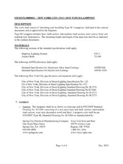
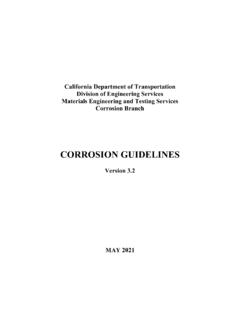
7 Install two or more reaction piles, or anchors, for the reaction frame (Fig. 1) after the installation of the test pile. For driven piles, locate these reaction piles not less than 10 ft. (3 m) or the sum of 5 reaction pile diameters and 5 test pile diameters (whichever of the two criteria is the greater distance) from the test pile or reference beam supports. For drilled shafts or micropiles, locate these reaction piles not less than 10 ft. (3 m) or 5 reaction pile diameters (whichever of the two criteria is the greater distance) from the test pile or reference beam supports. These distances are measured between the faces of the test pile and reaction piles. Anchors, if used, must be designed with sufficient free length so as not to interfere with the load test pile or the reference system. Design the reaction frame and reaction piles to resist four times the pile design load indicated in the contract documents without undergoing a magnitude of deflection exceeding 75 percent of maximum travel of the jack.
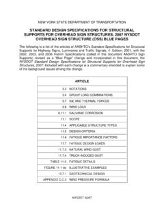
8 EB 15-025 Page 6 of 55 Plan View Section A-A Section B-B Figure 1 Typical Setup for a Reaction Frame EB 15-025 Page 7 of 55 2. Weighted Box or Platform. Construct a weighted box or platform (Fig. 2) over the test pile, supported on cribbing or on other piles installed after the test pile. a. Cribbing Support: For driven piles, drilled shafts or micropiles, locate the nearest face of the cribbing support not less than 10 ft. (3 m) or 5 test pile diameters (whichever of the two criteria is the greater distance) from the test pile or reference beam supports. Measure these distances between the test pile face and the nearest face of the cribbing supports. A greater spacing between the cribbing supports and test pile or reference system may be required to prevent foundation stresses caused by the cribbing from affecting the test.
9 B. Pile Support: For driven piles, locate these support piles not less than 10 ft. (3 m) or the sum of 5 support pile diameters and 5 test pile diameters (whichever of the two criteria is the greater distance) from the test pile or reference beam supports. For drilled shafts or micropiles, locate these support piles not less than 10 ft. (3 m) or 5 reaction pile diameters (whichever of the two criteria is the greater distance) from the test pile or reference beam supports. Measure these distances between the test pile face and the nearest face of the pile supports. Design the load beam and transfer beam to resist four times the pile design load indicated in the contract documents, without undergoing a magnitude of deflection exceeding 75 percent of maximum travel of the jack. Load the weighted box or platform with earth, sand, concrete, water, pig iron, or other suitable material to obtain a total weight of at least four times the pile design load indicated in the contract documents.
10 The load beam for a reaction frame may bear on the load transfer beam with no connections. The load beam may need stiffeners at the points of bearing. The beam may need truss work, not shown in the figure, to prevent excessive bending and resulting ram extension in excess of the seventy-five percent (75%) of the maximum travel of the jack. The pressure intensity exerted on the ground surface from any cribbing must not exceed the bearing capacity of the soil or cause settlement of the test pile and/or measurement system. EB 15-025 Page 8 of 55 Figure 2 Typical Setup for a Weighted Box or Platform 3. Alternative Methods. The Contractor may request approval to apply the reaction load by another method. In that case, submit in writing a summary of the alternative loading system with appropriately detailed drawings for approval by the B.