Transcription of STEADY HEAT CONDUCTION - Wright State University
1 STEADY heat CONDUCTIONIn heat transfer analysis, we are often interested in the rate of heat transferthrough a medium under STEADY conditions and surface temperatures. Suchproblems can be solved easily without involving any differential equationsby the introduction of the thermal resistance conceptin an analogous mannerto electrical circuit problems. In this case, the thermal resistance correspondsto electrical resistance, temperature difference corresponds to voltage, and theheat transfer rate corresponds to electric start this chapter with one-dimensional STEADY heat conductionin aplane wall, a cylinder, and a sphere, and develop relations for thermal resis-tancesin these geometries. We also develop thermal resistance relations forconvection and radiation conditions at the boundaries. We apply this conceptto heat CONDUCTION problems in multilayerplane walls, cylinders, and spheresand generalize it to systems that involve heat transfer in two or three dimen-sions.
2 We also discuss the thermal contact resistanceand the overall heattransfer coefficientand develop relations for the critical radius of insulationfor a cylinder and a sphere. Finally, we discuss STEADY heat transfer fromfinned surfacesand some complex geometrics commonly encountered inpractice through the use of CONDUCTION shape you finish studying this chapter,you should be able to: Understand the concept of thermalresistance and its limitations, and develop thermal resistancenetworks for practical heat CONDUCTION problems, Solve STEADY CONDUCTION problemsthat involve multilayer rectangular,cylindrical, or spherical geome-tries, Develop an intuitive understand-ing of thermal contact resistance,and circumstances under which itmay be significant, Identify applications in which insulation may actually increaseheat transfer, Analyze finned surfaces, and as-sess how efficiently and effectivelyfins enhance heat transfer, and Solve multidimensional practicalheat CONDUCTION problems usingconduction shape 1/5/10 11.
3 53 AM Page 135136 STEADY heat CONDUCTION3 1 STEADY heat CONDUCTION IN PLANE WALLSC onsider STEADY heat CONDUCTION through the walls of a house during a winterday. We know that heat is continuously lost to the outdoors through the intuitively feel that heat transfer through the wall is in the normal direc-tionto the wall surface, and no significant heat transfer takes place in the wallin other directions (Fig. 3 1).Recall that heat transfer in a certain direction is driven by the temperaturegradientin that direction. There is no heat transfer in a direction in whichthere is no change in temperature. Temperature measurements at several loca-tions on the inner or outer wall surface will confirm that a wall surface isnearly is, the temperatures at the top and bottom of a wallsurface as well as at the right and left ends are almost the same. Therefore,there is no heat transfer through the wall from the top to the bottom, or fromleft to right, but there is considerable temperature difference between the in-ner and the outer surfaces of the wall, and thus significant heat transfer in thedirection from the inner surface to the outer small thickness of the wall causes the temperature gradient in that di-rection to be large.
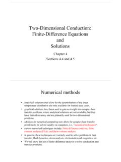
4 Further, if the air temperatures in and outside the house re-main constant, then heat transfer through the wall of a house can be modeledas steadyand temperature of the wall in this case de-pends on one direction only (say the x-direction) and can be expressed as T(x).Noting that heat transfer is the only energy interaction involved in this caseand there is no heat generation, the energy balancefor the wall can be ex-pressed asorin out (3 1)But dEwall/dt= 0 for steadyoperation, since there is no change in the temper-ature of the wall with time at any point. Therefore, the rate of heat transfer intothe wall must be equal to the rate of heat transfer out of it. In other words,therate of heat transfer through the wall must be constant,cond, wall a plane wall of thickness Land average thermal conductivity two surfaces of the wall are maintained at constant temperatures of T1andT2. For one-dimensional STEADY heat CONDUCTION through the wall, we haveT(x).
5 Then Fourier s law of heat CONDUCTION for the wall can be expressed ascond, wall kA (W)(3 2)where the rate of CONDUCTION heat transfer cond, walland the wall area Aare QdTdx Q QdEwalldt Q Q Rate ofheat transferinto the wall Rate ofheat transferout of the wall Rate of changeof the energyof the wall Q 20 C20 C20 C20 C20 C20 C3 C3 C3 C3 C3 C3 C3 C3 C3 C3 C3 C3 C3 C3 C3 C3 C3 C3 C20 C20 C11 C11 C11 C11 C11 C11 C11 C11 CAxzyT(x)FIGURE 3 1 heat transfer through a wall is one-dimensional when the temperature ofthe wall varies in one direction 3 2 Under STEADY conditions,the temperature distribution in a plane wall is a straight (x)Qcond Aconstant. Thus dT/dx constant, which means that the temperature throughthe wall varies linearly with is, the temperature distribution in the wallunder STEADY conditions is a straight line(Fig. 3 2). 1/5/10 11:53 AM Page 136137 CHAPTER 3 Separating the variables in the preceding equation and integrating from x 0, where T(0) T1, to x L,where T(L) T2, we getcond, walldx kA dTPerforming the integrations and rearranging givescond, wall kA (W)(3 3)which is identical to Eq.
6 1 21. Again,the rate of heat CONDUCTION through a plane wall is proportional to the average thermal conductivity, the wallarea, and the temperature difference, but is inversely proportional to the wall , once the rate of heat CONDUCTION is available, the tem-peratureT(x) at any location xcan be determined by replacing T2in Eq. 3 3 by T,and Lby Resistance ConceptEquation 3 3 for heat CONDUCTION through a plane wall can be rearranged ascond, wall (W)(3 4)whereRwall (K/W)(3 5)is the thermal resistanceof the wall against heat CONDUCTION or simply theconduction resistanceof the wall. Note that the thermal resistance of amedium depends on the geometryand the thermal propertiesof the that thermal resistance can also be expressed as Rwall T/cond, wall, QLkAT1 T2 Rwall QT1 T2L Q T2T T1 Q Lx 0T2(a) heat flow(b) Electric current flowRReV2T1V1T1 T2 RQ = V1 V2 ReI =FIGURE 3 3 Analogy between thermal andelectrical resistance is the ratio of the driving potential Tto the corresponding transfer ratecond, equation for heat transfer is analogous to the relation for electric current flow I,expressed asI (3 6)where Re L/seA is the electric resistanceand V1 V2is the voltage dif-ferenceacross the resistance (seis the electrical conductivity).
7 Thus, the rateof heat transferthrough a layer corresponds to the electric current,thethermal resistancecorresponds to electrical resistance,and the temperaturedifferencecorresponds to voltage differenceacross the layer (Fig. 3 3).Consider convection heat transfer from a solid surface of area Asand tem-perature Tsto a fluid whose temperature sufficiently far from the surface is T ,with a convection heat transfer coefficient s law of cooling for con-vection heat transfer rate conv hAs(Ts T ) can be rearranged asconv (W)(3 7)Ts T Rconv Q QV1 V2Re 1/7/10 10:04 AM Page 137whereRconv (K/W)(3 8)is the thermal resistanceof the surface against heat convection, or simply theconvection resistanceof the surface (Fig. 3 4). Note that when the convec-tion heat transfer coefficient is very large (h ), the convection resistancebecomes zeroand Ts T . That is, the surface offers no resistance to convec-tion,and thus it does not slow down the heat transfer process.
8 This situation isapproached in practice at surfaces where boiling and condensation occur. Alsonote that the surface does not have to be a plane surface. Equation 3 8 for con-vection resistance is valid for surfaces of any shape, provided that the as-sumption of h constant and uniform is the wall is surrounded by a gas, the radiation effects,which we haveignored so far, can be significant and may need to be considered. The rate ofradiation heat transfer between a surface of emissivity eand area Asat tem-perature Tsand the surrounding surfaces at some average temperature Tsurrcanbe expressed asrad esAs( ) hradAs(Ts Tsurr) (W)(3 9)whereRrad (K/W)(3 10)is the thermal resistanceof a surface against radiation, or the radiation resistance,andhrad es( (Ts Tsurr)(W/m2 K)(3 11)is the radiation heat transfer coefficient. Note that both Tsand Tsurrmustbein K in the evaluation of hrad. The definition of the radiation heat transfer co-efficient enables us to express radiation conveniently in an analogous mannerto convection in terms of a temperature difference.)
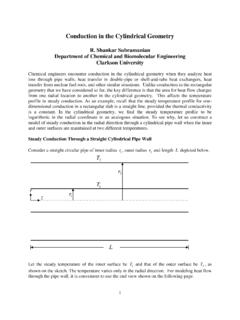
9 But hraddepends stronglyon temperature while hconvusually does surface exposed to the surrounding air involves convection and radiationsimultaneously, and the total heat transfer at the surface is determined byadding (or subtracting, if in the opposite direction) the radiation and convec-tion components. The convection and radiation resistances are parallel to eachother, as shown in Fig. 3 5, and may cause some complication in the thermalresistance network. When Tsurr T , the radiation effect can properly be ac-counted for by replacing hin the convection resistance relation byhcombined hconv hrad(W/m2 K)(3 12)where hcombinedis the combined heat transfer coefficientdiscussed in Chapter 1. This way all complications associated with radiation are )T2s QradAs(Ts Tsurr)1hrad AsTs TsurrRradT4surrT4s Q1hAs138 STEADY heat CONDUCTIONS olidQ T hAsT TsRconv =1 hAsTsFIGURE 3 4 Schematic for convection resistance at a AsTsQconv RconvT Qrad Q = Qconv + Qrad RradTsurrFIGURE 3 5 Schematic for convection andradiation resistances at a 1/5/10 11:53 AM Page 138 Thermal Resistance NetworkNow consider STEADY one-dimensional heat transfer through a plane wall ofthickness L, area A, and thermal conductivity kthat is exposed to convectionon both sides to fluids at temperatures T 1and T 2with heat transfer coeffi-cients h1and h2, respectively, as shown in Fig.
10 3 6. Assuming T 2 T 1,thevariation of temperature will be as shown in the figure. Note that the temper-ature varies linearly in the wall, and asymptotically approaches T 1and T 2inthe fluids as we move away from the STEADY conditions we haveor h1A(T 1 T1) kA h2A(T2 T 2)(3 13)which can be rearranged as (3 14)T 1 T1 Rconv, 1 T1 T2 Rwall T2 T 2 Rconv, 2T 1 T11/h1A T1 T2L/kA T2 T 21/h2A QT1 T2L Q Rate ofheat convectioninto the wall Rate ofheat conductionthrough the wall Rate ofheat convectionfrom the wall 139 CHAPTER 3 ThermalnetworkElectricalanalogyQ T1T2 Rconv,2 Rconv,1 RwallRe,3Re,1 IRe,2T 2V2T 1V1T 1 T 2 Rconv,1 + Rwall + Rconv,2Q = V1 V2 Re,1 + Re,2 + Re,3I =WallT2T1T 2T 1 FIGURE 3 6 The thermal resistance network for heat transfer through a plane wall subjected to convection on both sides,and the electrical 1/5/10 11:53 AM Page 139 Once the rate of heat transfer is calculated, Eq. 3 14 can also be used to determine the intermediate temperatures T1or T2.