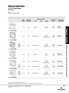
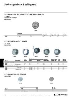
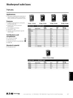
Transcription of Steel City Metallic Boxes & Covers - USESI Careers
1 Steel City Metallic Boxes & CoversIn this City Metallic Boxes & CoversOverview ..A-2 A-5 Pre-Fab Components and Assemblies ..A-6 A-16 Switch Boxes and Accessories ..A-17 A-28 Round/Octagon Boxes and A-33 Ceiling Fan Boxes and Accessories ..A-34 A-35 Square Boxes and Accessories ..A-36 A-49 Utility Boxes and Accessories ..A-50 A-51 Handy Boxes and Accessories ..A-51 A-52 Gang Boxes and Accessories ..A-52 A-55 Concrete/Masonry Boxes and Accessories ..A-56 A-58 Box Hangers and Supports ..A-59 A-61 Stud Wall and Drywall Accessories ..A-62 StatesTel: : ServicesTel: & Covers Steel City Metallic BoxesAdvantages of Steel City Boxes and CoversNotched Ears on Switch Boxest Steel City Switch Boxes feature a longer ear and a special notch. This provides clearance for the screws that are used to attach wall plates to GFCI or rocker-type light switchesRaised Ground Screw Bump in 4" Square, 411 16" and Utility Boxest Quicker surface mounting by eliminating the need to remove the portion of the screw that threads through the back of the boxt Allows for improved repositioning of grounding conductort Ground bump standard in 21 8" boxest Ground bump optional in 11 2" boxesMS Bracket Boxest Mounts without the use of screwst Mounts to the open or closed side of the studt Works on stud depths up to 4"Pre-Installed Screws are Packaged in Raised Positiont Eliminates extra step of having to back out the screw during cover installationSteel City switch and outlet Boxes are protected from rust and corrosion by zinc-galvanizing.
2 All clamps and other component parts are electrogalvanized separately, before assembly in the box, to ensure corrosion protection of every surface. Steel City galvanized finish meets the requirements of Underwriters Laboratories, Inc. and Federal Knockouts on Square Boxest Provide better contact with conduit fitting and locknut to the box, improve grounding path, stronger than 3 4" knockoutt Available in all four standard-size square boxest Improved 3 4" knockout position on square boxest Less labor required to install 3 4" conduit to boxSteel City is the industry-leading product line of Metallic switch and outlet Boxes used in electrical construction. Since 1904, Steel City products have symbolized the highest quality standards in manufacturing and innovative design, with one of the most complete offerings City products are known for their simple improve ments, such as being the first box offering to standardize combination slotted/phillips screws on all Boxes .
3 Thomas & Betts is also recognized as a leader in design innovation, as in our new metal stud & Betts continues to listen to contractors and responds to their ever-changing needs. Contact a T&B distributor nearest you to select the right Steel City product for your City Metallic Boxes and CoversUnited StatesTel: : ServicesTel: & Covers Steel City Metallic BoxesOverviewGuide to Steel City Knockouts, Pryouts, Ears, Brackets and ClampsKnockouts and PryoutsSteel City conduit KOs have standard trade size dimensions. KOs are uniform and true for attachment of cable or conduit connectors. Pryouts for cable entrance are slotted a twist with a screwdriver removes them. KOs and Pryouts are precision stamped to permit easy removal, but remain sufficiently strong and sturdy when not Box EarsMounting ears support the box independent of the electrical system attachments. Switch Boxes have a fixed ear for old work for plaster are set 1 16" forward of the box face in position for old work (modernization), except where specifically Holes for GroundingAll Steel City Boxes have a 10-32 tapped hole in the bottom of the box for attaching separate ground 4" Conduit KO1" Conduit KOKnockouts DV TypeMounts box offset from stud 11 2".
4 613 16" long x 1" wide x 11 2" offsetMS Type (For Metal Studs)Mounts to any depth of metal stud, open or closed side. 21 2" long x 111 16" wide x 3 8" offset;Far side support to 4" onlyS or B TypeMounts to face of stud. Used on switch, handy or square Boxes . 2" long x 21 8" wideT TypePositions handy box against the face and side of stud. 51 2" long x 7 8" wideSV TypeMounts box to side of stud with positioning spikes. 73 8" long x 1" wide x 3 8" offsetCV Type (Outlet Boxes )Mounts to flat side of metal studs or wood studs. 73 8" long x 1" wide x 3 8" offset7 8"13 32"13 8"1 2" Conduit KOC-5C-1C-8(Loom only)C-10C-3L TypeUsed to mount octagon Boxes . 25 8" long x 35 8" wide x 1 4" offsetFor Non- Metallic Sheathed Cable and Non- Metallic Tubing (Loom)UNDERWRITERS LABORATORIES INC. and CANADIAN STANDARDS ASSOCIATION file numbers for individual items available upon Armored CableListing Information for Armored Cable Clamp Type C-3 Armored Cable (BX) SteelSizes 14-2 through 10-3 Armored Cable (BX) AluminumSizes 14-2 through 10-3MC Interlocked (MCI).
5 570 DiameterMC Interlocked (MCI) .606 DiameterMC Corrugated (MCC) .515 DiameterMCAP Aluminum*.370 .580 Flex Metal Conduit Steel1 8" Trade SizeFlex Metal Conduit Aluminum3 8" Trade SizeC-3 Clamp Acceptable for Grounding* MCAP is a trademark of Southwire CompanyEccentric Knockouts Combination 1 2" & 3 4" KnockoutPryouts Cable Pryouts Always in Pairs21 32"V TypeMounts to flat side of stud. 73 8" long x 1" wide x 3 8" offset Products listed in this catalog are subject to alteration or discontinuation without prior notice. StatesTel: : ServicesTel: & Covers Steel City Metallic BoxesArticle 314 of the National Electrical Code Covers the installation and use of Boxes . The article includes table references that guide the electrician in the selection of the proper box size necessary to safely accommodate electrical service requirements. The box capacity table shown (page A-5) is reproduced in part from the NEC as a quick reference and guide. The NEC should be consulted for complete ReferenceArticle 314 Boxes and Number of Conductors in Outlet, Device, and Junction Boxes , and Conduit Bodies.
6 Boxes and conduit bodies shall be of sufficient size to provide free space for all enclosed conductors. In no case shall the volume of the box, as calculated in (A), be less than the fill calculation as calculated in (B). The minimum volume for conduit bodies shall be as calculated in (C).The provisions of this section shall not apply to terminal housings supplied with motors or generators. Informational Note: For volume requirements of motor or generator terminal housings, see Article Boxes and conduit bodies enclosing conductors #4 AWG or larger shall also comply with the provisions of (A) Box Volume Calculations. The volume of a wiring enclosure (box) shall be the total volume of the assembled sections and, where used, the space provided by plaster rings, domed Covers , extension rings and so forth, that are marked with their volume or are made from Boxes the dimensions of which are listed in Table (A).(1) Standard Boxes . The volumes of standard Boxes that are not marked with their volume shall be as given in Table (A).
7 (2) Other Boxes . Boxes 1650 cm3 (100 ) or less, other than those described in Table (A), and nonmetallic Boxes shall be durably and legibly marked by the manufacturer with their volume. Boxes described in Table (A) that have a volume larger than is designated in the table shall be permitted to have their volume marked as required by this section.(B) Box Fill Calculations. The volumes in paragraphs (B)(I) through (B)(5), as applicable, shall be added together. No allowance shall be required for small fittings such as locknuts and bushings.(1) Conductor Fill. Each conductor that originates outside the box and terminates or is spliced within the box shall be counted once, and each conductor that passes through the box without splice or termination shall be counted once. Each loop or coil of unbroken conductor not less than twice the minimum length required for free conductors in shall be counted twice. The conductor fill shall be calculated using Table (B). A conductor, no part of which leaves the box, shall not be : An equipment grounding conductor or conductors not over four fixture wires smaller than #14 AWG, or both, shall be permitted to be omitted from the calculations where they enter a box from a domed luminaire or similar canopy and terminate within that box.
8 (2) Clamp Fill. Where one or more internal cable clamps, whether factory or field supplied, are present in the box, a single volume allowance in accordance with Table (B) shall be made based on the largest conductor present in the box. No allowance shall be required for a cable connector with its clamping mechanism outside the box.(3) Support Fittings Fill. Where one or more luminaire studs or hickeys are present in the box, a single volume allowance in accordance with Table (B) shall be made for each type of fitting based on the largest conductor present in the box.(4) Device or Equipment Fill. For each yoke or strap containing one or more devices or equipment, a double volume allowance in accordance with Table (B) shall be made for each yoke or strap based on the largest conductor connected to a device(s) or equipment supported by that yoke or strap. A device or utilization equipment wider than a single 50mm (2 in.) device box as described in Table (A) shall have double volume allowances provided for each gang required for mounting.
9 (5) Equipment Grounding Conductor Fill. Where one or more equipment grounding conductors or equipment bonding jumpers enter a box, a single volume allowance in accordance with Table (B) shall be made based on the largest equipment grounding conductor or equipment bonding jumper present in the box. Where an additional set of equipment grounding conductors, as permitted by (D), is present in the box, an additional volume allowance shall be made based on the largest equipment grounding conductor in the additional set.(C) Conduit Bodies.(1) General. Conduit bodies enclosing #6 AWG conductors or smaller, other than short-radius conduit bodies as described in (C)(2), shall have a cross-sectional area not less than twice the cross-sectional area ofthe largest conduit or tubing to which they can be attached. The maximum number of conductors permitted shall be the maximum number permitted by Table 1 of Chapter 9 for the conduit or tubing to which it is attached.(2) With Splices, Taps or Devices.
10 Only those conduit bodies that are durably and legibly marked by the manufacturer with their volume shall be permitted to contain splices, taps or devices. The maximum number of conductors shall be calculated in accordance with (B). Conduit bodies shall be supported in a rigid and secure manner.(3) Short-Radius Conduit Bodies. Conduit bodies such as capped elbows and service-entrance elbows that enclose conductors #6 AWG or smaller, and are only intended to enable the installation of the raceway and the contained conductors, shall not contain splices, taps or devices and shall be of sufficient size to provide free space for all conductors enclosed in the conduit StatesTel: : ServicesTel: & Covers Steel City Metallic BoxesTable (B) Volume Allowance Required per ConductorSIZE OF CONDUCTOR (AWG) FREE SPACE WITHIN BOX FOR EACH with permission from National Fire Protection Association NFPA70-2011. National Electrical Code, Copyright 2010, National Fire Protection Association, Quincy, MA 02269.