Transcription of Steel Edge Shelving Assembly Instructions
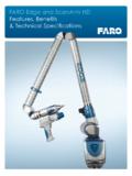
1 Stand the post against a wall with the fronts of the posts facing away from each other. Insert a pair of side braces into the second set of angles slots from each end of the posts. Use one side brace on each side of post. On posts 8 ft. high use a third pair of braces at the center of the posts. Step 2 Step 2 WideNarrowUpStep 3 Drive all the braces to the bot-tom of the slots with a hammerStep 4 Use a large screwdriver to twist the post s locking tab over the side brace to lock it in upright frames upside down to install plastic end caps or optional Steel footplates to bottom of posts. Wait until Shelving is completely assembled before putting the caps on the top of the braces fit into second set of slots down from top of braces fit into second set of slots up from bottom of ft. high posts or higher get a third set of side braces at the locking tabEnd Frames over 8 ft.
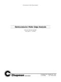
2 High see back Edge Shelving Assembly InstructionsUpright Frame Assembly :Step 1 Determine which end of the post goes up. The keystone slots on the front face of the post are wider at the top than at the bottom. Step 5 Snap plastic end caps into the bottom of End Caps:Optional Steel Footplates:Place footplate over post bottom. Slide 3/16 x 1-1/2 cotter pin through the hole on side of the footplate and the square hole at bottom of the cotter pin to lock in second upright frame in position and hook shelf bars into the first upright frame (right side up) in position and hook the bottom shelf bars into the lowest posi-tion on the 6 Step 7 Unit with standard duty shelf barsUnit with heavy duty shelf barsHook in remaining shelf bars at the desired levels. If Heavy Duty shelves are being used, drop in the #200 series shelf 8HD Shelf SupportAssembling shelves to the end frames:Step 11 Step 9 Drop MDF panels between shelf barsStep 10 Bolt back brace to rear of posts.
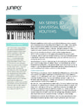
3 For rows 8 high or less only one back brace needed per row. (Back braces are not used on 3 high sections.)Repeat steps 6, 7, 8, & 9 for the remaining sections in the row. Back braces are NOT required for addtitional sections in the row for units 8 ft. high or less. For units over 8 ft high see the back page for installation 12 Press #080 End cap on to the top of each back page for Assembly of units 9 , 10 and 12 tallUse a carpenter s level to check that the posts are plumb and shelves level. If not, shim under posts to make them so. This is mandatory for safe 13 Assembly of Shelving Units 9 to 12 feet high8 10 46 2 Post Section#089 Splice Bar1/4-20 x Bolt & Nut10 Post SectionTop View#089 Splice channel fits inside posts12 side braces where shown to avoid interference with back bracing10 46 8 9 & 10 ft. 4 Section Row2 Section Row3 Section RowSingleSection50 86 74 38 14 50 14 Lowest round hole in pattern for rows 5 sections or BRACINGUPRIGHT FRAMES 9 ft.
4 And higherA back brace is required for each section 9 ft. high and higher. Locate braces where shown for maximum stability. Bolt only through small round holes in post face. Back to back sections share a common back brace . Use #051 back to back connec-tors for necessary clearance between TO BACK ASSEMBLYOn rows back to back use part #051 row spacer to couple frames together. This keeps 1 clear between posts for shelf adjustment. Install one halfway up each place where frames !!!Wall anchoring is required when the height of the top loaded shelf exceeds 4 times the depth of the unit.#051 row spacerSteel Edge Shelving Part Identification#080 End Cap - clips to the top and bottom of each #800 series post.#800 series Post#900 series Side Brace - Installed in pairs. Attaches to the side of the front and rear #800 series posts to build Frame Parts:#600 series Back BraceInstalled diagonally between #800 series posts across back of Shelving unit.
5 Only one needed per row for Shelving units 8 high or less. For Shelving units 9 high or more one brace needed for every Parts:#700 series Standard Duty Shelf BarMeasures 1-1/4 high. Attach to the end frame on the front and back to hold MDF decking.#700 series Heavy Duty Shelf BarMeasures 1-3/4 high. Attach to the end frame on the front and back. Used with the #200 series shelf support to hold MDF decking.#200 series Heavy Duty Shelf SupportUsed with the Heavy Duty Shelf Bar to support decking in back of the shelf bar used to hold #200 series shelf support.#S030-A Anchor FootplateAnchors post to floor. Uses one (included) 3/16 x 1-1/2 cotter : All Scotland Rack products are designed in accordance with the American National Standard ANSI for hand loaded Shelving . They are not designed to resist the impact from powered lift equip-ment and should not be used in areas where powered lift equipment is Ratings are the maximum permissible loads and must never be exceeded.
6 The published Load Ratings are for evenly distributed loads. If the shelves are loaded asymmetrically the actual capacity of the shelf may be substantially less. In accordance with ANSI , hand loaded shelves are NOT designed or tested to resist impact loads including those which may be imposed by man aboard or automatic storage/retrieval : It is the end user s responsibility to provide adequate flooring support for the system and its ap-plication. Upright frame Assembly anchoring will be required when the top loaded shelf is over eight feet high and the height to depth ratio of the Shelving unit exceeds four (4). When the upright frame Assembly ratio is exceeded, back-to-back sections should be firmly tied together at a minimum of two places (near the top and the bottom), and single row sections should be attached to some firm restraint such as the floor, wall, or tied over-head across the aisle to an opposite upright frame Assembly .
7 Depth relates to the overall depth (front to back) of the upright frame Assembly and height refers to the height from the floor to the highest of the upright frame Assembly or top of the load on the section, both in the same units of attachment to the building structure is required for stability, these forces must be checked on the struc-ture to assure its capacity of resisting these additional forces. Also, it is possible that certain local codes do not allow attachment to a building structure, and therefore other means for stabilization must be must be installed with a maximum tolerance from the vertical of one-half inch in ten feet or more of height unless tighter tolerances are : The owner shall maintain the structural integrity of the installed Shelving system by assuring proper operational, housekeeping, and maintenance procedures including but not limited to the following:(1) Prohibit any overloading of any shelf positions and of the overall Shelving system.
8 (2) Regularly inspect for damage. If damage is found, immediately unload the affected area and re place or repair any damaged columns, beams or other structural components.(3) Require that all goods stored on each shelf be properly stacked and Requirements for Steel Edge Shelving