Transcription of Steering - centralstatesbus.com
1 Steering Overview This section will address those parts of the Steering system related to the: Steering wheel Steering column Power Steering fluid requirements Steering gear (TAS 55). Hydraulic Steering pump Pitman Drag link Tie rod (cross tube). Tie rod ends Lubrication requirements Appendixes In This Chapter Appendix 1. TAS Steering gear (Exerpt). This four page exerpt from TRW's Steering gear Service manual includes fluid information, an exploded parts diagram, and torque specifications for the TAS55 Steering gear . Appendix 2. Popped Adjustment. This four page TRW Service Bulletin explains on- vehicle poppet readjustment procedure.
2 Appendix 3. TRW Steering Maintenance. This TRW publication, entitled Chart Your Way To Easy Steering , provides a solid overview of potential Steering problems, their diagnosis and correction. [Warning] Hydraulic fluid must be handled, stored and disposed of in a manner consistent with all the applicable local, state, and federal guidelines concerning hazardous materials. The hydraulic pump for the power assist is located on the engine. The configuration of piping from the pump to the Steering gear is dependent on whether the bus has hydraulic brakes or an air brake system. 821. On Visions equipped with air brakes, the power Steering fluid flows to the steer- ing gear , and returns directly to the reservoir.
3 On Visions equipped with hydraulic brakes, the power Steering fluid flows from the reservoir into the power Steering gear . The pressurized fluid is then directed to the hydraulic brake power assist (booster). From there, the power Steering fluid is returned to the reservoir, under lower pressure. Torque from the Steering wheel is transmitted through the Steering column to the Steering gear . The TAS 55 Steering gear assists the efforts of the driver. [Caution] The power Steering fluid and the brake fluid are not the same. They must be kept separate. Use DOT 3 for the brake system and use Dexron III. for the power Steering fluid.
4 POPPET. ADJUSTMENT. TRW Steering TAS. MAINTENANCE Steering gear . 3 2 1. APPENDIX APPENDIX APPENDIX L. Vision [propane] service manual Other oils are acceptable for the power Steering system; however, the system must be drained and flushed to use any of these. (See the appropriate TRW Service manual for a complete list.) Do not mix oils or fluids if you change the fluid. The reservoirs are mounted on the firewall, near the Steering column. The brake reservoir has two filler caps, and stands away from the firewall due to the electrically operated emergency brake boost pump assembly. Steering System Maintenance Before attempting to work on the Steering gear , or any portion of the Steering sys- tem, you must stabilize the vehicle.
5 Read and understand the Warnings and Cautions in the General Maintenance chapter of this manual . Regularly check the fluid fluid level in the power Steering reservoir. Change the fluid and replace the filter at the intervals specified in the Specs & Maintenance chap- ter. Clean around the reservoir filler cap before removing it. Dirt and other foreign matter can damage the hydraulic system. Do not bend or straighten any Steering component or linkage. Never attempt to weld any broken Steering component. Do not use a torch to remove any Steering component. Use only original equipment replacement parts. Never use high pressure or steam to clean the power Steering gear while on or off the bus.
6 Doing so can force contaminants inside the gear and lead to malfunction. Proper alignment of the Steering column is important to assure smooth Steering . Correct the cause of any free play, rattle, or shimmy immediately to avoid damage to the Steering system. Record and report any malfunctions or accidents which may have damaged Steering components. Axle Stop Adjustment Adjustment of the axle stops should be made after tow-in has been set on the front axle. 1. With the front tires on turn-angle plates, center the left front tire in the 822 straight ahead position using alignment equipment, then set the turn-angle plates to zero.
7 2. Set the axle stops to allow 50 of full right and full left steerage. Check for adequate clearance between tires and wheelwells. Lock the axle stop jam nuts after adjusting the axle stops. 3. Remove the turn-angle plates. Verify that the axle stops contact the axle pads at full right-hand and left-hand turns. It may be necessary to relieve tire flex by rolling the bus forward or backward, in order to make the axle stops con- tact. There must be at least 1/4-inch clearance between the pitman arm, drag rod and front axle tie rod, and all potential interference points. Setting the Steering Poppets To adjust the Steering poppets, refer to Appendix 2 in this chapter.
8 L. Steering Toe-In Adjustment Set the toe in with no weight in the bus. The curb weight of the vehicle should be on the ground. Toe should be checked at the tires front and rear center, at a distance above the ground equal to the rolling radius of the tires. The toe must be 1/16 1/32. (.06 .03 ). 1. Adjust the toe by turning the tie rod cross tube. 2. When the correct toe is achieved, tighten the pinch bolts at the tie rod ends. Torque the pinch bolts to 50 60 ft. lbs. ( Nm). Steering Lubrication Points Use NLGI #2 EP and greases rated GC LB, or equivalent. Refer to the Specs & Mainte- nance chapter for service intervals.
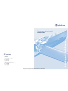
9 The Steering gear . (Use only hand grease gun to lube the Steering gear .). Both ends of the draglink. Top and bottom of the King-pin. Both ends of the tie-rod. The slack adjuster. The cam brake housing. King-Pin Lubrication The suspension must be loaded prior to lubrication. Either place the bus on the ground or lift by the wheels; not the axles. 1. Clean off all the grease fittings with clean shop towel prior to lubrication. 2. Lubricate the King pins through the fittings at the top and bottom of the King pin. 3. Force the proper lubricant into the upper and lower grease fittings until 823. grease flows from the purge locations.
10 Greasing at the lower zerk should purge lubricant from the thrust bearing shell. The right hand side (curb side). King Pin Grease Purge Locations of the axle has a steel roller thrust bearing; the left hand side has a composite thrust bearing. Both purge in the same area. Tie-Rod Lubrication 1. Turn the bus wheels straight ahead. 2. Clean the zerk fittings at each end. L. Vision [propane] service manual 3. Wipe the seal/boot clean as well. 4. Attach a grease gun to the zerk fitting. Either a hand or air operated grease gun may be used. If an air operated grease gun is used, the system air pres- sure should not exceed 150 psi (1035 kPa).