Transcription of Step11-Static Load Testing - Vickars
1 Copyright 2003 Hubbell, Screw Foundation System Design Manual for New Construction Chance Company11-1 Step 11 Static load TestingTest loading is the most definitive method of determining load capacity of a pile. Testing apile to failure provides valuable information to the design engineer and is recommendedfor load tests performed prior to the foundation design. Such Testing permits the selectionof both the optimum helical screw foundation and the design D-1143, Standard Test Method for Piles Under Static Axial Compressive load ,latest revision, should be used. This method is applicable to all types of deep foundationsthat function in a manner similar to piles regardless of their method of installation.
2 It doesnot specify a particular method to be used, but rather provides several optional Testing during DesignLoad test results are useful tools for the helical screw foundation designer. They confirm atheoretically designed foundation and allow for site-specific correlation between capacityand installing torque (For more details on Installation Torque/ load Capacity Relationship,see Step 9).The test pile, installation equipment and installation procedure should be identical to thatintended to be used for production piles to the extent piles should be loaded to at least two times the design load , and preferably to foundations, including helical screw foundations, that have been tested totheir ultimate capacity should not be used as production Pile TestConducting a load test on battered helical screw foundations can be difficult.
3 Withapproval of the responsible engineer, the results from a test on a vertical foundationinstalled to the same vertical depth, same helical configuration and similar installationtorque as the battered foundation may be used to evaluate the axial capacity of thebattered MethodsQuoting the Canadian Foundation Engineering Manual, 1985: The slow- Testing methods .. (outlined by the ASTM D1143 Standard) .. are verytime-consuming. When the objective of the test is to determine the bearing capacityof the pile, these methods can actually make the data difficult to evaluate anddisguise the pile true load movement behaviour, thereby counteracting the objectiveof the test.
4 The benefit of the (slow) test methods lies in the additional soil-pilebehaviour information, occasionally obtained, which the interpreting engineer canuse, when required, in an overall evaluation of the piles.. For routine Testing and proof Testing purposes, the quick methods .. aresufficient. Where the objective is to determine the bearing capacity of the pile ..the quick test is technically preferable to the slow methods. Quick load Test Method for Individual Piles(For complete description refer to ASTM D1143 81 subsection )Apply the load in increments of 10 to 15% of the proposed design load with a constant timeinterval between increments of 21 2 minutes or as otherwise specified.
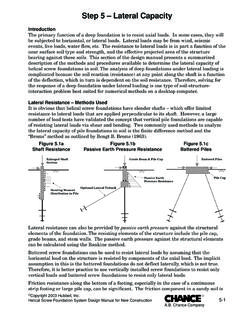
5 Add increasing loadincrements until continuous jacking is required to maintain the test load or until the11-2 Copyright 2003 Hubbell, Screw Foundation System Design Manual for New Construction Chance Companycapacity of the loading apparatus is reached, whichever occurs first. At this time, stop thejacking. After a 5 minute interval or as otherwise specified, remove the full load from thepile in four approximately equal decrements with 5 minutes between decrements so theshape of the rebound curve may be Apparatus for Applying Compressive load (see Figure )The apparatus for applying compressive test load to a helical screw foundation should beconstructed so that the load is applied concentrically to the axis of the loading may cause foundation cap rotation and horizontal displacement;consequently, every effort should be made to minimize any eccentricity.
6 A calibrated loadcell or jacking system shall be used to measure the load . If the latter is used, the completejacking system (including the hydraulic cylinder, hydraulic pump and pressure gauge)shall be calibrated as a is suggested that a square bearing plate be centered on top of the helical screwfoundation between the jack and the top of the foundation. The plate should be sized sothat, with the ram placed at its center, sufficient area remains in the corners to allowproper placement and function of the dial indicators. A smooth bearing surface (such asglass) is required for the dial indicator stems. A second steel bearing plate of sufficientsize and thickness is centered on top of the hydraulic cylinder/ram that will bear againsthe centered test a load cell is used, it is centered on top of the bearing plate.
7 Then a second upperFigure - Test Frame for Applying Compressive Load7 ft (2 m) minimumBetween Test Pile and Reaction AnchorReaction Anchor(4 minimum)CribbingLoad BeamSpreader BeamHydraulic Jack/CylinderDial IndicatorReference Beams Copyright 2003 Hubbell, Screw Foundation System Design Manual for New Construction Chance Company11-3bearing plate is centered on top of the load cell and bears against the centered test space should be provided between the foundation cap and soil to eliminate anyunwanted support from the soil surface during AnchorsTypically, four helical tension anchors provide support for the test frame and resist thetest load as it is applied.
8 All reaction anchors should be installed to approximately thesame depth and installation torque. The combined ultimate capacity of the reactionanchors should be twice the intended test pile DeflectionA minimum of two dial indicators with at least 2" inches of travel measure the deflectionof the test pile. Each dial indicator is mounted on a separate reference beam. Thesereference beams are typically parallel and must be independent of the test frame andcribbing. The reference beams are placed on each side of the foundation to be tested sothat the dial indicators can be mounted equidistant from the center and on opposite sidesof the test types of measuring systems may be used such as a wire-mirror-scale system,surveyor s level or laser beam.
9 The measuring system must have proven reliability withan accuracy of " ( mm). It is recommended to use a secondary deflection measuringsystem as a for the Quick load Test MethodRecord readings of load , time and settlement immediately before and after each loadincrement or decrement. All deflection devices should be read simultaneously or as closeto simultaneously as CriteriaAcceptance of the load test results is generally governed by the building code for thatjurisdiction and subject to review by thestructural designer. The structuraldesigner determines the maximumdeflection the structure can withstandwithout undue loss of function ordistress.
10 The acceptance criteria must bedefined prior to conducting the load load -deflection data may be plottedfor a fast overview of the results. shows a sample test plot. Variousbuilding codes have their ownacceptance criteria, generally a limit ondeflection at the factored load . A fastway to determine the ultimate load is byuse of a technique called the intersection of tangents. This is accomplished bygraphically constructing two tangent lines. One line is drawn tangent to the second straight line portion of the load curve. The other line is drawn tangent to the initial straight line portion of the load -deflection curve which is beyond the curved or non-linearportion of the load -deflection curve.