Transcription of Stepper Motor Theory of Operation - Gyan
1 Stepper Motor Theory of Operation Stepper motors provide a means for precise positioning and speed control without the use of feedback sensors. The basic Operation of a Stepper Motor allows the shaft to move a precise number of degrees each time a pulse of electricity is sent to the Motor . Since the shaft of the Motor moves only the number of degrees that it was designed for when each pulse is delivered, you can control the pulses that are sent and control the positioning and speed. The rotor of the Motor produces torque from the interaction between the magnetic field in the stator and rotor. The strength of the magnetic fields is proportional to the amount of current sent to the stator and the number of turns in the windings. The Stepper Motor uses the Theory of Operation for magnets to make the Motor shaft turn a precise distance when a pulse of electricity is provided.
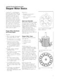
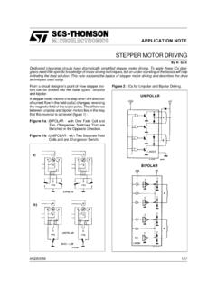
2 You learned previously that like poles of a magnet repel and unlike poles attract. Figure 1 shows a typical cross-sectional view of the rotor and stator of a Stepper Motor . From this diagram you can see that the stator (stationary winding) has eight poles, and the rotor has six poles (three complete magnets). The rotor will require 24 pulses of electricity to move the 24 steps to make one complete revolution. Another way to say this is that the rotor will move precisely 15 for each pulse of electricity that the Motor receives. The number of degrees the rotor will turn when a pulse of electricity is delivered to the Motor can be calculated by dividing the number of degrees in one revolution of the shaft (360 ) by the number of poles (north and south) in the rotor.
3 In this Stepper Motor 360 is divided by 24 to get 15 . When no power is applied to the Motor , the residual magnetism in the rotor magnets will cause the rotor to detent or align one set of its magnetic poles with the magnetic poles of one of the stator magnets. This means that the rotor will have 24 possible detent positions. When the rotor is in a detent position, it will have enough magnetic force to keep the shaft from moving to the next position. This is what makes the rotor feel like it is clicking from one position to the next as you rotate the rotor by hand with no power applied. Fig 1. Diagram that shows the position of the six-pole rotor and eight-pole stator of a typical Stepper Motor . When power is applied, it is directed to only one of the stator pairs of windings, which will cause that winding pair to become a magnet.
4 One of the coils for the pair will become the North Pole, and the other will become the South Pole. When this occurs, the stator coil that is the North Pole will attract the closest rotor tooth that has the opposite polarity, and the stator coil that is the South Pole will attract the closest rotor tooth that has the opposite polarity. When current is flowing through these poles, the rotor will now have a much stronger attraction to the stator winding, and the increased torque is called holding torque. By changing the current flow to the next stator winding, the magnetic field will be changed 45 . The rotor will only move 15 before its magnetic fields will again align with the change in the stator field. The magnetic field in the stator is continually changed as the rotor moves through the 24 steps to move a total of 360.
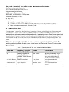
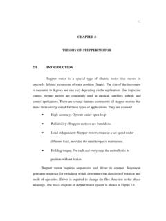
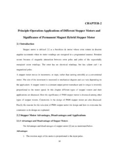
5 Figure 2. shows the position of the rotor changing as the current supplied to the stator changes. FIGURE 2. Movement of the Stepper Motor rotor as current is pulsed to the stator. (a) Current is applied to the A and A' windings, so the A winding is north, (b) Current is applied to B and B'. windings, so the B winding is north, (c) Current is applied to the C and C' windings, so the C winding is north, (d) Current is applied to the D and D' windings so the D winding is north. (e) Current is applied to the A and A' windings, so the A' winding is north. In Fig. 2a you can see that when current is applied to the A and A' stator windings, they will become a magnet with the top part of the winding being the North Pole, and the bottom part of the winding being the South Pole.
6 You should notice that this will cause the rotor to move a small amount so that one of its south poles is aligned with the north stator pole (at A), and the opposite end of the rotor pole, which is the north pole, will align with the south pole of the stator (at A'). A line is placed on the south-pole piece so that you can follow its movement as current is moved from one stator winding to the next. In Fig. 2b current has been turned off to the A and A windings, and current is now applied to the stator windings shown at the B and B' sides of the Motor . When this occurs, the stator winding at the B' position will have the polarity for the south pole of the stator magnet, and the winding at the B position will have the north-pole polarity. In this condition, the next rotor pole that will be able to align with the stator magnets is the next pole in the clockwise position to the previous pole.
7 This means that the rotor will only need to rotate 15 in the clockwise position for this set of poles to align itself so that it attracts the stator poles. In Fig. 2c you can see that the C and C' stator windings are again energized, but this time the C winding is the north pole of the magnetic field and the C' winding is the south pole. This change in magnetic field will cause the rotor to again move 15 in the clockwise position until its poles will align with the C and C' stator poles. You should notice that the original rotor pole that was labeled 1 now moved three steps in the clockwise position. In you can see that the D and D' stator windings are energized, the winding at D position is the north pole. This change in polarity will cause the rotor to move another 15 in the clockwise direction.
8 You should notice that the rotor has moved four steps of 15 each, which means the rotor has moved a total of 60 from its original position. This can be verified by the position of the rotor pole that has the line on it, which is now pointing at the stator winding that is located in the 2 o'clock position. In you can see that the A and A' stator windings are energized, the winding at A position is the south pole. This change in polarity will cause the rotor to move another 15 in the clockwise direction. You should notice that the rotor has moved four steps of 15 each, which means the rotor has moved a total of 75 from its original position. Thus the sequence of energizing ABCDA will move the rotor in the clockwise direction. It can be easily verified that for the counter clockwise direction the sequence should be ADCBA.
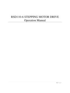
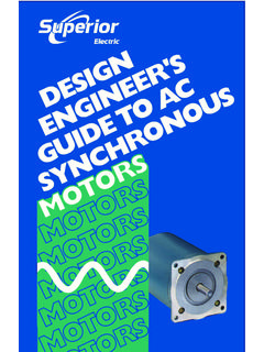
9 Stepper Motor Switching Sequence The Stepper Motor can be operated in three different stepping modes, namely, full-step, half-step, and micro- step. Full-Step The Stepper Motor uses a four-step switching sequence, which is called a full-step switching sequence which is already described above. Half-Step Another switching sequence for the Stepper Motor is called an eight-step or half-step sequence. The switching diagram for the half-step sequence is shown in Fig. 3. The main feature of this switching sequence is that you can double the resolution of the Stepper Motor by causing the rotor to move half the distance it does when the full-step switching sequence is used. This means that a 200-step Motor , which has a resolution of , will have a resolution of 400 steps and.
10 The half-step switching sequence requires a special Stepper Motor controller, but it can be used with a standard hybrid Motor . The way the controller gets the Motor to reach the half-step is to energize both phases at the same time with equal current. FIGURE 3 The switching sequence for the eight-step input (half-step mode). In this sequence the first step has SW1 is on, and SW2,SW3 and SW4 are off. The sequence for the first step is the same as the full-step sequence. The second step has SW1 and SW2 are on and all of the remaining switches are off. This configuration of switches causes the rotor to move an additional half-step because it is acted upon by two equal magnetic forces and the rotor turns to the equilibrium position which is half a step angle.