Transcription of Steps for proper installation and operation - Bendix
1 1 Bendix ACom Diagnostic SoftwareStarter GuideSteps for proper installation and operationBendix ACom Diagnostic SoftwareStarter Guide2 GENERAL SAFETY GUIDELINESWARNING! PLEASE READ AND FOLLOW THESE INSTRUCTIONSTO AVOID PERSONAL INJURY OR DEATH:When working on or around a vehicle , the following guidelines should be observed AT ALL TIMES: Park the vehicle on a level surface, apply the parking brakes and always block the wheels. Always wear personal protection equipment. Stop the engine and remove the ignition key when working under or around the vehicle . When working in the engine compartment, the engine should be shut off and the ignition key should be removed.
2 Where circumstances require that the engine be in operation , EXTREME CAUTION should be used to prevent personal injury resulting from contact with moving, rotating, leaking, heated or electrically-charged components. Do not attempt to install, remove, disassemble or assemble a component until you have read, and thoroughly understand, the recommended procedures. Use only the proper tools and observe all precautions pertaining to use of those tools. If the work is being performed on the vehicle s air brake system, or any auxiliary pressurized air systems, make certain to drain the air pressure from all reservoirs before beginning ANY work on the vehicle . If the vehicle is equipped with a Bendix AD-IS air dryer system, a Bendix DRM dryer reservoir module, or a Bendix AD-9si air dryer, be sure to drain the purge reservoir.
3 Following the vehicle manufacturer s recommended procedures, deactivate the electrical system in a manner that safely removes all electrical power from the vehicle . Never exceed manufacturer s recommended pressures. Never connect or disconnect a hose or line containing pressure; it may whip and/or cause hazardous airborne dust and dirt particles. Wear eye protection. Slowly open connections with care, and verify that no pressure is present. Never remove a component or plug unless you are certain all system pressure has been depleted. Use only genuine Bendix brand replacement parts, components and kits. Replacement hardware, tubing, hose, fi ttings, wiring, etc.
4 Must be of equivalent size, type and strength as original equipment and be designed specifi cally for such applications and systems. Components with stripped threads or damaged parts should be replaced rather than repaired. Do not attempt repairs requiring machining or welding unless specifi cally stated and approved by the vehicle and component manufacturer. Prior to returning the vehicle to service, make certain all components and systems are restored to their proper operating condition. For vehicles with Automatic Traction Control (ATC), the ATC function must be disabled (ATC indicator lamp should be ON) prior to performing any vehicle maintenance where one or more wheels on a drive axle are lifted off the ground and moving.
5 The power MUST be temporarily disconnected from the radar sensor whenever any tests USING A DYNAMOMETER are conducted on a vehicle equipped with a Bendix Wingman system. You should consult the vehicle manufacturer's operating and service manuals, and any related literature, in conjunction with the Guidelines ACom Diagnostic Software + Minimum Requirements A computer with the minimum system requirements to run Bendix ACom diagnostic software - see Appendix 3. The latest version of Bendix ACom diagnostic software installed. ACom software is available for download at An RP1210 data link or Power Line Communication (PLC) adapter with the latest drivers and firmware installed.
6 A powered, fully functioning J1939 or PLC diagnostics port on the host vehicle or trailer. Keys to the vehicle and a fully charged vehicle battery, or an auxiliary battery tender, to support extended ignition - ON Starting The ACom Software IMPORTANTC onfirm you are working with genuine Bendix parts. Look for the Bendix label and part number before you Insert the key in the ignition and turn it to the 3rd position On / Run (not to be confused with Engine Start). The dash display should light up and the vehicle will begin its electronic readiness check, as well as the chuff test, if it is equipped with air brakes. Wait until the chuff test is completed or a minimum of 40 seconds after turning the Plug the J1939 diagnostic harness adapter of your Data Link unit into the vehicle diagnostics port this port is usually found under the dash, in the driver-side left corner knee-space or along the left side of the driver seat mounting rail.
7 For PLC, locate the trailer interface port at the front of the trailer. 3. Your Data Link Adapter (DLA) should show a power ON light and possible blinking of a J1939 data light. Plug the DLA into your Start the ACom software by double clicking the Bendix ACom software shortcut on your the Bendix ACom Starter InterfaceStepScreen1. Press the Communication Device icon and select your RP1210 or PLC adapter from the list of installed drivers*. This only needs to be done once as long as you continue to use the same DLA adapter on your PC. The device list will only show items for which proper drivers have been installed on your system. Press the green check mark to exit the screen.
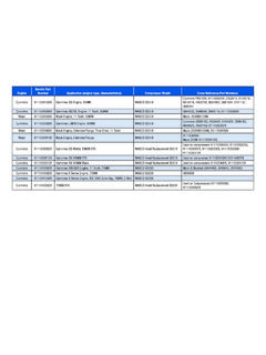
8 *For a list of compatible devices, please refer to Appendix Now select the Electronic Control Unit (ECU) that you wish to diagnose from the ECU list on the starter main the required ECU is not on the list, press the Detect ECU button and wait for the detection cycle to complete. In order for an ECU to be detected, it must be powered and currently connected to the J1939 CAN bus. For a complete list of all ECUs available and their use please refer to the table in Apendix 1. on the Start with ECU button after you ve highlighted the ECU in the ACom software will now begin to communicate with the selected ECU. This can take several minutes depending on CAN bus traffic and the state of the you receive an ECUtalk Platform Error during the application loading time, you must check your connections, drivers, ports and CAN load.
9 For additional information on this, please refer to Appendix additional Starter functions, please refer to Appendix 4; *For a list of compatible devices, please refer to Appendix with Device is Established Next StepsDepending on the nature of the ECU and the complexity of the system you re connecting to, here are some features you can expect to see when using the Bendix ACom diagnostic the ACom Software Can DoProvide a view of ECU / system status with current user settings, safety parameters and active / inactive a view of any active Diagnostic Trouble Codes (DTCs).Clear the DTCs if the problem is access to user programmable access to configure certain system and safety and print diagnostic reports and event background safety and user data including past DTCs, system alerts, and major certain systems, such as radar and camera , as applicable, diagnostics of onboard changing of the sensor software-based addition or removal of activation or deactivation of changing of in-cab display configurations, such as units and menu sound output control for certain ECUs / devices / self-diagnostics and simulated performance alerts, blink codes, sounds, etc.
10 To verify system functions and auxiliary devices such as lights and examples of ACom diagnostic software applications are, but not limited to, Bendix Wingman Advanced - A Collision Mitigation Technology, Bendix Wingman Fusion , SmarTire Tire Pressure Monitoring System (TPMS) by Bendix CVS, Bendix ESP Full-Stability Technology, Bendix Antilock Brake Systems (ABS), Bendix Trailer Antilock Air Brake Systems (TABS), following is a listing of what the ACom software cannot the ACom Software Cannot DoRepair electrical or mechanical hardware access to more than one ECU, device or system at a multiple versions of the ACom software at the same to more than one data link or PLC adapter at a recorded or deactivate system critical alerts and the reduction of safety parameters beyond reasonable system critical previously recorded event data or device serial 1 Each ECU and its FunctionBendix ECUD escriptionUseEC-60 Bendix EC-60 ABS (Standard) / ATC (Premium) / ESP (Advanced)
