Transcription of Stiffness Methods for Systematic Analysis of Structures
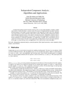
1 Stiffness Methods for Systematic Analysis of Structures (Ref: Chapters 14, 15, 16)The Stiffness method provides a very Systematic way of analyzing determinate and indeterminate Structures . Displacement ( Stiffness ) MethodExpress local (member) force)displacement relationships in terms of unknown member displacements. Using equilibriumof assembled members, find unknown displacements. Unknowns are usually displacements Coefficients of the unknowns are " Stiffness " coefficients. RecallConvert the indeterminate structure to a determinate one by removing some unknown forces / support reactions and replacing them with (assumed) known / unit forces. Using superposition, calculate the force that would be required to achieve compatibilitywith the original structure. Unknowns to be solved for are usually redundant forces Coefficients of the unknowns in equations to be solved are "flexibility" coefficients. Force (Flexibility) MethodDirectly gives desired displacements and internal member forces Easy to program in a computer Additional steps are necessary to determine displacements and internal forces Can be programmed into a computer, but human input is required to select primary structure and redundant forces.
2 Example:Express FMin terms of displacements of Iand J Assemble ALL members and enforce EQUILIBRIUM to find displacements. Overall idea: StiffnessMethod Page 1 Degrees of Freedom( Kinematic Indeterminacy)Member and Node Connectivity: StiffnessMethod Page 2 Transformation of Vectors (Displacements or Forces) between Global and Local coordinatesGlobal displacements with Local (member) deformations, and Local member forces back to Global force equilibrium, In order to relate: we need to be able to transform between these 2 co)ordinate axes freely:Global and Local (member) co)ordinate axes StiffnessMethod Page 3 Local (Member) Force)Displacement RelationshipsThese LOCAL (member) force)displacement relationships can be easily established for ALL the members in the truss, simply by using given material and geometric properties of the different members. StiffnessMethod Page 4 ASSEMBLY of LOCAL force)displacement relationships for GLOBAL EquilibriumThe member forces that were expressed in the LOCAL coordinate system, cannot be directly added to one another to obtain GLOBAL equilibrium of the must be TRANSFORMED from LOCAL to GLOBALand then added together to obtain the global equilibrium equations for the structure which will allow us to solve for the unknown displacements.
3 StiffnessMethod Page 5 ASSEMBLY of LOCAL force)displacement relationships for GLOBAL EquilibriumNow ALL the member force)displacement relationships can be ASSEMBLED (Added) together to get Global equilibrium:Note that "q" are forces on members, so to get forces on nodes we must take ")q".Each one of the 10 equations above must sum to ZERO for global equilibrium. StiffnessMethod Page 6 Solution of unknown displacements at "free dofs"and reactions at "specified dofs"Rearranging: StiffnessMethod Page 7 MATLAB Code for 2D Truss Analysis using the Stiffness MethodInput File StiffnessMethod Page 8 MATLAB Code for 2D Truss Analysis using the Stiffness Method(Continued)Calculation of Local and Global Element Stiffness Matrices StiffnessMethod Page 9 Support at node 1 settles down by the force in member = 8x10⁶ NExampleScreen clipping taken: 4/9/2014 9:37 AMScreen clipping taken: 4/9/2014 9:37 AMScreen clipping taken: 4/9/2014 9:37 AMKglobal = Solution: Displacements:Reactions.
4 Kglobal = Force in Member 2 Displacement of member 2 StiffnessMethod Page 10 Inclined Support ConditionsSometimes, the support conditions are not oriented along global x)y these cases, one must transform specific components of the global equilibrium equations to match the orientation of the inclined supports so that the boundary conditions can be enforced of freedom 3 and 4 need to be rotated to 3'' and 4'' StiffnessMethod Page 11 Find displacements and EA = 1 ExampleKGKG' Solution: StiffnessMethod Page 12 Effect of Temperature Changes and Fabrication ErrorsChanges in lengths of truss members due to temperature or fabrication errors can also be accommodated in the Analysis by applying equivalent nodal forcesthat would result from these a member has change in length EL (either due to fabrication error or due to temperature EL= ET L) then the equivalent nodal forcesthat will need to be applied to the truss will be: StiffnessMethod Page 13 Member 2 is too short by the force in member = 8x10⁶ NExampleSolutionKglobal = Force in member 2: StiffnessMethod Page 14 Space (3D) Truss AnalysisFor space (3D) trusses, all the same concepts of 2D truss Analysis still dofs per node Transformation matrix becomes 3x3 The main differences are:Coordinate Transformation StiffnessMethod Page 15 Example StiffnessMethod Page 16 Stiffness method for BeamsThe overall methodology of the Stiffness Methods is still the same for problems involving beams:Define the geometryof the problem in terms of nodes and up the degrees of freedom: transverse displacements and rotations at the loadingand boundary conditionsas externally applied forces and moments, and degrees of freedom that are fixed / up element force)displacement relations qM= KM.
5 DM4.(local and global coordinate systems are the same)Assemble forces and moments from all elements in terms of unknown global displacements and by partitioning the free and specified degrees of freedom as Elements and Degrees of Freedom StiffnessMethod Page 17 Element force)displacement relationship StiffnessMethod Page 18 StiffnessMethod Page 19 StiffnessMethod Page 20 StiffnessMethod Page 21 Sample MATLAB code StiffnessMethod Page 22 PlottingElement Calculations StiffnessMethod Page 23 Assembly and Global solutionKA= KB= KG= Assembly of global Stiffness matrix :Load:Solution: StiffnessMethod Page 24 ExampleSupport B settles by the reactions and draw the Shear Force and Bending Moment Diagrams of the = 29000 ksi ; I = 750 in4K1 = K2 = K3 = Assembled Kglobal = Solution: StiffnessMethod Page 25 Distributed Loads along the length of the elementBeams with distributed loads along the length can be solved by the Stiffness method using fixed)end moments as follows:Determine = 29000 ksi; I = 510in4 ExampleK2 = K3 =Global system to solve: StiffnessMethod Page 26 StiffnessMethod Page 27 Stiffness Method for Frame StructuresFor frame problems (with possibly inclined beam elements), the Stiffness method can be used to solve the problem by transforming element Stiffness matricesfrom the LOCAL to GLOBAL that in addition to the usual bending terms, we will also have to account for axial effects.
6 These axial effects can be accounted for by simply treating the beam element as a truss element in the axial direction. StiffnessMethod Page 28 Transformation from Local to Global coordinatesEach node has 3 degrees of freedom:But Thus transformation rules derived earlier for truss members between (X, Y)and (X',Y')still hold:Transformation matrix Tdefined above is the same as QrotTdefined in the provided MATLAB := QrotTQrotConverting Local co)ordinates to Global:(Qrot)(Qrot)(Qrot)(Qrot) StiffnessMethod Page 29 Element Stiffness matrix in GLOBAL coordinates:Substituting the transformation relations (l) and (2) into LOCAL force (moment) )displacement (rotation) relationships (L): (QrotT)(QrotT)(Qrot)(Qrot)TmatrixT(in MATLAB code)Tmatrix (in MATLAB code)Thus, similar to trusses:Example: StiffnessMethod Page 30 Frame 2D MATLAB Code: StiffnessMethod Page 31 Plotting StiffnessMethod Page 32 Frame Element CodeScreen clipping taken: 4/30/2014 8:40 AM StiffnessMethod Page 33 Example:Element Stiffness matrices.
7 (local coordinates)(Global Co)ordinates) StiffnessMethod Page 34 Global structural Stiffness matrix (15 15) :Solution: StiffnessMethod Page 35