Transcription of STRENGTH PROPERTIES OF ROCKS AND ROCK MASSES 1 ...
1 STRENGTH PROPERTIES OF ROCKS AND ROCK MASSES . 1. INTRODUCTION. 2. TESTING OF INTACT ROCK FOR STRENGTH . Uniaxial Compression Point Load Testing Uniaxial Tension Indirect Tension Tests Shear Tests Confined Compression Tests (Triaxial Tests). Biaxial and Multiaxial Tests Other Tests 3. PARAMETERS AFFECTING ROCK STRENGTH . 4. FAILURE CRITERIA FOR INTACT ROCKS AND ROCK MASSES . Mohr Criterion Mohr-Coulomb Criterion Hoek and Brown Criterion Other Criteria Effect of Water on STRENGTH 5. REFERENCES. CVEN 5768 -Lecture Notes 8 Page 1. B. Amadei 1. INTRODUCTION. For civil and mining engineering projects that involve ROCKS either as construction or foundation materials, a question which often arises in practice is: "will the combination of initial stresses and stresses induced by the construction and operation of an engineering structure produce rock failure and what will be the extent of the failure zone". In order to answer that question, it is necessary to know how the stresses are redistributed due to the rock-structure interaction and what is the rock mass STRENGTH .
2 Knowledge of rock mass STRENGTH is also important in the design of support systems as discussed in the next set of notes with regard to the concept of rock- support interaction. In general, rock mass STRENGTH depends on the STRENGTH of intact rock and the STRENGTH of rock discontinuities. In general, compared to intact rock, a rock mass has reduced tensile STRENGTH (almost zero), and reduced shear STRENGTH especially along discontinuity planes. Furthermore, if a rock mass is cut by directional joint sets, the rock mass STRENGTH is anisotropic. Rock mass STRENGTH is scale dependent and varies with the volume of rock under consideration. The modes of failure of intact rock are multiple. Rock can fail in tension, compression or shear. This depends on the load configuration, the geometry of the problem and how the loads are applied and distributed. A rock mass can also fail in tension, compression or shear. However, the failure may involve the intact rock only, the discontinuities only, or may be mixed and involve both the intact rock and the discontinuities.
3 2. TESTING OF INTACT ROCK FOR STRENGTH . Uniaxial Compression Recall the typical stress strain response curve for a specimen of intact rock under uniaxial compression (see Figure 1 in Lecture Notes 5). Part OA represents the closing of existing cracks in the rock and an overall readjustment of the rock testing machine setup whereas part AB. represents the elastic rock response. Using AE (acoustic emission) devices, it has been found that starting at point B microcracks develop in the rock sample and the sample experiences strain hardening. The ordinate of point B is called the yield stress by analogy with the response of concrete samples. The maximum ordinate of the curve (Point C) that marks the transition between strain hardening and softening is called the unconfined compressive STRENGTH of the rock and is denoted as Co or qu. Failure takes place continuously from C to D during which macrocracking takes place as the rock becomes more deteriorated and crack coalescence takes place.
4 Various authors have compiled the values of the unconfined compressive STRENGTH for different rock types (Balmer, 1953; Johnson and DeGraff, 1988; Hatheway and Kiersch, 1989; Goodman, 1989; ). Typical values are given in Tables 1 and 2. CVEN 5768 -Lecture Notes 8 Page 2. B. Amadei Granite Basalt Gneiss Schist Quart- Marble Lime- Sand- Shale zite stone stone Av. Co Max. Co Min. Co Range No. of samples 26 16 24 17 7 9 51 46 14. Table 1. Typical values of uniaxial STRENGTH (in MPa) for nine common rock types (after Johnson and Degraff, 1988). Rock Tensile STRENGTH Compressive STRENGTH (MPa) (MPa). Limestone (20) (4). Sandstone (23) (5). Sandstone (19) (10). Sandstone (8) (4). Mudstone (4) (4). Limestone (24) (5). Limestone (23) (8). Ironstone (5) (4). Sandstone (11) (5). Table 2. Mean tensile STRENGTH and compressive STRENGTH for selected sedimentary rock types (after Johnson and Degraff, 1988). The behavior of intact rock in the post-peak domain is not a true rock property and is partially dependent on the stiffness of the loading system.
5 A testing machine consists of an assembly of cross heads, tie bars, platens, screws and hydraulic cylinders, pipes and hydraulic oil contributing on their own to the total machine stiffness. By using stiff testing machines (low energy stored), or more recently servo-controlled testing machines, it is possible to observe the post-peak response of ROCKS (Hudson et al., 1971). Otherwise, for soft machines (high energy stored) sudden failure may take place at point C. In the field, the stiffness of the testing machine is replaced by the stiffness of the rock mass surrounding the volume of rock of interest. Uniaxial compression tests require a careful test set-up and strict specimen preparation. Requirements for specimen preparation and testing are discussed in ASTM D-2938-86 and in the ISRM suggested methods (Bieniawski and Bernede, 1979). End effects can also be important especially if the load platens are not chosen accordingly. End platens can create CVEN 5768 -Lecture Notes 8 Page 3.
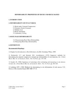
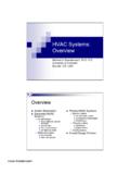
6 B. Amadei lateral restraint and a stress state far from being uniaxial. Lubricants can also be used such as teflon. However their effectiveness has been put in doubt at several occasions since they can initiate longitudinal splitting. The ideal platens would be made out of a medium that has same lateral expansion as the rock being tested. Point Load Testing In order to overcome many of the problems associated with the unconfined compression test, Broch and Franklin (1972) proposed a testing method called the Point Load Test. The test consists of squeezing pieces of rock diametrically between two hardened steel cones. The test set-up is shown in Figure 1. For these tests, rock pieces must have a length at least times their diameter (Figure 2a). The point load index, Id, is equal to (1). where P is the load at rupture and D is the core diameter. Rock specimens break since tensile cracks develop parallel to the loading direction. In general, it has been found that the value of the load P at failure depends largely on the core diameter.
7 Hence, the results of point load tests are usually presented in terms of a reference diameter equal to 50 mm. If the diameter is not equal to 50 mm, a correction is required (Figure 3). The unconfined compressive STRENGTH qu is related to the point load index with 50 mm cores Is50 as follows (2). Beside the diametral test, the axial test and the irregular lump test have also been proposed (see Figures 2b and 2c). STRENGTH anisotropy can also be assessed by using the point load index as suggested by Broch (1983) who proposed an anisotropy index Ia equal to (3). Uniaxial Tension direct measurements of tensile STRENGTH are difficult. Gripping systems or the use of cement at the test specimen ends can produce unwanted stress concentrations and create premature failure. More recently, strong structural epoxies are available to carry out uniaxial tension tests. The testing procedure is described in ASTM D 2936-84 and in Bieniawski and Hawkes (1978). Indirect Tension Tests CVEN 5768 -Lecture Notes 8 Page 4.
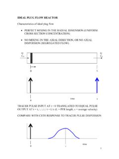
8 B. Amadei Difficulties associated with performing direct uniaxial tension tests have led to a number of indirect methods such as the splitting tension test (also called Brazilian or diametral compression test) and the flexural tests. The Brazilian Test The test consists of applying diametral compression to induce tensile stresses in a thin disc of rock. As shown in Figure 4a, a line load creates a uniform tensile stress across the loaded diameter accompanied with a vertical compressive stress. Failure is assumed to start at the center under a state of stress (4). where P is the applied load, D is the core diameter and t the core thickness. Equation (4) can only be used if the rock is isotropic. If the rock is anisotropic, equation (4) is replaced by equation (28) in Lecture Notes 5. When using the Brazilian test to determine the indirect tensile STRENGTH of rock, it is usually assumed that failure is the result of the uniform tensile stress normal to the splitting diameter (see Figure 4a) and that the tensile STRENGTH , To, is given by the value of F3 (= -To) at failure (5).
9 Special precautions must be taken at the contact between the rock and the loading platens to avoid crushing that could throw doubts as to the mechanism of failure in the test sample. Strips of paper or steel loading jaws (Figure 4c) are often used to replace the point load by a strip load over an angle not exceeding 10 (Figure 4b). It can be shown that the stress distribution is only affected near the surface contacts but not in the body of the disc specimens, and in particular at their center. Flexural Tests Flexural tests are conducted by bending cylindrical or prismatic rock beams. Three point or four point flexural loading tests can be conducted. For the geometry shown in Figures 5a and 5b, the flexural STRENGTH (sometimes called the modulus of rupture) is calculated as the maximum tensile stress existing on the lower fiber of the beam at peak load. Using simple beam theory and three point loading (Figure 5a), the tensile STRENGTH is equal to CVEN 5768 -Lecture Notes 8 Page 5.
10 B. Amadei (6). and (7). for cylindrical and prismatic specimens respectively. In equations (6) and (7), P is the maximum applied load, L the length between supports, D the specimen diameter, a is the beam thickness and, b, is its width. For four point loading (Figure 5b), equation (6) is replaced by the following (8). Note that in general, the tensile STRENGTH measured using the indirect methods is less than that measured used a direct tension apparatus. Shear Tests direct simple, double or punch shear tests can be conducted on rock. The tests allow a direct measurement of the intact rock shear STRENGTH . However, they are difficult to perform. Confined Compression Tests (Triaxial Tests). Confined compression tests can be conducted using a confining vessel similar to the one used for measuring the STRENGTH of soils. The so-called Hoek cell is often used in this test. Figure 6a shows the original Hoek cell and Figure 6b is a modified confining cell developed at the University of Colorado at Boulder.