Transcription of Stress, Strain, and Strain Gages
1 Stress, Strain , and Strain Gages , Page 1 Stress, Strain , and Strain Gages Author: John M. Cimbala, Penn State University Latest revision: 24 October 2013 Introduction Stress and Strain are important aspects of Mechanical Engineering, especially in structural design. In this learning module, we discuss stress and Strain and their relationship, and how to measure them. Definitions Stress o When a material is loaded with a force, the stress at some location in the material is defined as the applied force per unit of cross-sectional area.
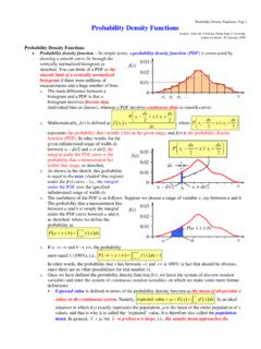
2 O For example, consider a wire or cylinder, anchored at the top, and hanging down. Some force F (for example, from a hanging weight) pulls at the bottom, as sketched, where A is the original cross-sectional area of the wire, and L is the original wire length. o In this situation, the material experiences a stress, called an axial stress, denoted by the subscript a, and defined as aFA . o Notice that the dimensions of stress are the same as those of pressure force per unit area. Strain o In the above simple example, the wire stretches vertically as a result of the force.
3 Strain is defined as the ratio of increase in length to original length. o Specifically, when force is applied to the wire, its length L increases by a small increment L, while its cross-sectional area A decreases, as sketched. o In the axial direction (the direction of the applied force), axial Strain a is defined as aLL . o The dimensions of Strain are unity Strain is a nondimensional quantity. Hooke s law o It turns out that for elastic materials, stress is linearly proportional to Strain . o Mathematically, this is expressed by Hooke s law, which states aaE , where E = Young s modulus, also called the modulus of elasticity.
4 O Young s modulus is assumed to be constant for a given material. o Hooke s law breaks down when the Strain gets too high. On a typical stress- Strain diagram, Hooke s law applies only in the elastic stress region, in which the loading is reversible. Beyond the elastic limit (or proportional limit), the material starts to behave irreversibly in the plastic deformation region, in which the stress vs. Strain curve deviates from linear , and Hooke s law no longer holds, as sketched. o In this learning module, only the elastic stress region is considered.
5 Wire resistance The electrical resistance R of a wire of length L and cross-sectional area A is given by LRA , where is the resistivity of the wire material. (Do not confuse with density, for which the same symbol is used.) The electrical resistance of the wire changes with Strain : o As Strain increases, the wire length L increases, which increases R. o As Strain increases, the wire cross-sectional area A decreases, which increases R. o For most materials, as Strain increases, the wire resistivity also increases, which further increases R.
6 The bottom line is that wire resistance increases with Strain . In fact, it turns out that at constant temperature, wire resistance increases linearly with Strain . Mathematically, aRSR , where S is the Strain gage factor, defined as /aRRS . S is typically around for commercially available Strain Gages . S is dimensionless. FAL FL + L LL a a elastic limit elastic stress region Yield stress Stress, Strain , and Strain Gages , Page 2 Strain gage The principle discussed above, namely that a wire s resistance increases with Strain , is key to understanding how a Strain gage works.
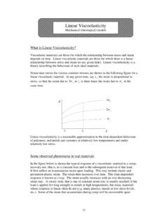
7 The Strain gage was invented by Ed Simmons at Caltech in 1936. A Strain gage consists of a small diameter wire (actually an etched metal foil) that is attached to a backing material (usually made of plastic) as sketched. The wire is looped back and forth several times to create an effectively longer wire. The longer the wire, the larger the resistance, and the larger the change in resistance with Strain . Here, four loops of metal foil are shown, providing an effective total foil length L that is eight times greater than if a single wire, rather than a looping pattern, were used.
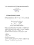
8 Commercially available Strain Gages have even more loops than this. The ones used in our lab have six loops. The direction of the applied Strain is indicated on the sketch. The connecting wires or leads go to an electronic circuit (discussed below) that measures the change in resistance. Consider a beam undergoing axial Strain ; the Strain is to be measured. A Strain gage is glued to the surface of the beam, with the long sections of the etched metal foil aligned with the applied axial Strain as sketched below left (the Strain gage is mounted on the front face of the beam).
9 As the surface stretches (strains), the Strain gage stretches along with it. The resistance of the Strain gage therefore increases with applied Strain . Assuming the change in resistance can be measured, the Strain gage provides a method for measuring Strain . Other practical applications are shown below a Strain gage glued (rather sloppily) onto a cylindrical rod, and a Strain gage mounted on a re-bar, which is then encased in concrete, used to measure shrinkage and to monitor the Strain on structural components in bridges, buildings, etc.
10 F Strain gage Beam Typical Strain gage values Here are some typical values for resistance, Strain gage factor, and Strain , along with the predicted values of change in resistance: o The electrical resistance R of a commercial Strain gage (with no applied Strain ) is typically either 120 or 350 . o The most widely used commercially available Strain Gages have R = 120 . o The Strain gage factor S of the metal foil used in Strain Gages is typically around o In typical engineering applications with metal beams, the range of axial Strain is 10-6 < a < 10-3.