Transcription of Stress – Strain Relationships - University of Arizona
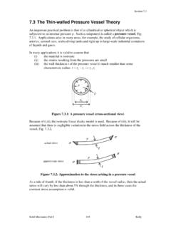
1 OPTI 222 Mechanical Design in Optical Engineering 17 Stress Strain Relationships Tensile Testing One basic ingredient in the study of the mechanics of deformable bodies is the resistive properties of materials. These properties relate the stresses to the strains and can only be determined by experiment. One of the simplest tests for determining mechanical properties of a material is the tensile test. In this test, a load is applied along the longitudinal axis of a circular test specimen. The applied load and the resulting elongation of the member are measured.
2 OPTI 222 Mechanical Design in Optical Engineering 18In many cases, the process is repeated with increased load until the desired load levels are reached or the specimen breaks. Load-deformation data obtained from tensile and/or compressive tests do not give a direct indication of the material behavior, because they depend on the specimen geometry. However, using the Relationships we previously discussed, loads and deformations may be converted to stresses and strains. PA = L = = normal Stress on a plane perpendicular to the longitudinal axis of the specimen P = applied load A = original cross sectional area = normal Strain in the longitudinal direction = change in the specimen s gage length L = original gage length The resulting Stress - Strain curve or diagram gives a direct indication of the material properties.
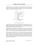
3 Note: Stress - Strain diagrams are typically based upon the original cross sectional area and the initial gage length, even though these quantities change continuously during the test. These changes have a negligible effect except during the final stages of the test. 2017-T451 Aluminum Alloy Load-deformation data Stress - Strain data Engineering Stress and engineering Strain are computed using the original specimen dimensions. OPTI 222 Mechanical Design in Optical Engineering 19 Ductile Material Test Specimen True Stress and true Strain are based upon instantaneous values of cross sectional area and gage length.
4 OPTI 222 Mechanical Design in Optical Engineering 20As shown in the previous diagram, the initial portion of the Stress - Strain diagram for most materials used in engineering structures is a straight line. For the initial portion of the diagram, the Stress is directly proportional to the Strain . Therefore, for a specimen subjected to a uniaxial load, we can write = E This relationship is known as Hooke s Law and was first recorded by Robert Hooke, an English mathematician, in 1678. Note: Hooke s Law describes only the initial linear portion of the Stress - Strain curve for a bar subjected to uniaxial extension.
5 The slope of the straight-line portion of the Stress - Strain diagram is called the Modulus of elasticity or Young s Modulus. E = / (normal Stress Strain ) G = / (shear Stress Strain ) E = Elastic Modulus or Modulus of elasticity G = Shear Modulus or Modulus of Rigidity Material Properties PL Proportional Limit - Stress above which Stress is not longer proportional to Strain .
6 EL Elastic Limit - The maximum Stress that can be applied without resulting in permanent deformation when unloaded. YP Yield Point - Stress at which there are large increases in Strain with little or no increase in Stress . Among common structural materials, only steel exhibits this type of response. YS Yield Strength - The maximum Stress that can be applied without exceeding a specified value of permanent Strain (typically .2% = .002 in/in). OPTI 222 Mechanical Design in Optical Engineering 21 U Ultimate Strength - The maximum Stress the material can withstand (based on the original area).
7 Material Properties E Modulus of elasticity - Slope of the initial linear portion of the Stress - Strain diagram. The modulus of elasticity may also be characterized as the stiffness or ability of a material to resist deformation within the linear range. E (Steel) 30 x 106 psi E (Aluminum) 10 x 106 psi Et Tangent Modulus - Slope of the Stress - Strain curve above the proportional limit. There is no single value for the tangent modulus; it varies with Strain . G Shear Modulus - Slope of the initial linear portion of the shear Stress - Strain diagram.
8 G (Steel) 12 x 106 psi G (Aluminum) 4 x 10⁶ psi Percent Elongation - The Strain at fracture in tension, expressed as a percentage = ((final gage length initial gage length)/ initial gage length) x 100. Percent elongation is a measure of ductility. Percent Reduction in Area - The reduction in cross-sectional area of a tensile specimen at fracture = ((initial area - final area)/ initial area) x 100. Percent reduction in area is also a measure of ductility. Isotropic Isotropic materials have elastic properties that are independent of direction.
9 Most common structural materials are isotropic. Anisotropic Materials whose properties depend upon direction. An important class of anisotropic materials is fiber-reinforced composites. Homogeneous A material is homogeneous if it has the same composition at every point in the body. A homogeneous material may or may not be isotropic. OPTI 222 Mechanical Design in Optical Engineering 22 Materials may be divided into two broad categories (ductile materials and brittle materials). Ductile Material Materials that are capable of undergoing large strains (at normal temperature) before failure.
10 An advantage of ductile materials is that visible distortions may occur if the loads before too large. Ductile materials are also capable of absorbing large amounts of energy prior to failure. Ductile materials include mild steel, aluminum and some of its alloys, copper, magnesium, nickel, brass, bronze and many others. Brittle Material Materials that exhibit very little inelastic deformation. In other words, materials that fail in tension at relatively low values of Strain are considered brittle. Brittle materials include concrete, stone, cast iron, glass and plaster.