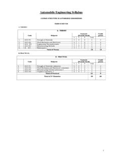
Transcription of Structural Stability and Determinacy
1 1 Structural Stability and Determinacy Stability is an essential precondition for a structure to be able to carry the loads it is subjected to, and therefore being suitable for Structural analysis. Since Structural analysis is based on solving the unknown forces (or displacements) within a structure using some equations, it is essentially the comparison of the equations and unknowns that determine the Stability of a Structural system. Statical Determinacy of a structure is a concept closely related to its Stability . Once a structure is determined to be stable, it is important to determine whether it remains in equilibrium; , if it can be analyzed by the concepts of statics alone, particularly for hand calculation.
2 Although this information is not essential in the context of computer-based Structural analysis, there are important differences between structures that are solvable by statics alone and those requiring additional information (usually from kinematics). The number of external reactions is often the simplest means to determine the Stability of a structure . They must be greater than the number of equations available for the structure to remain in static equilibrium. The number of equations for two-dimensional (planar) structures ( , 2D trusses and 2D frames) is three ( , Fx = 0, Fy = 0, Mz = 0), while it is six ( , Fx = 0, Fy = 0, Fz = 0, Mx = 0, My = 0, Mz = 0) for three-dimensional (non-coplanar) structures ( , 3D trusses and 3D frames).
3 The number of equations of static equilibrium may be increased for structures with internal hinges (h), each providing an additional equation for BM = 0. Therefore Stability requires the number of equations to be greater than (The number of equations of statics + h); , (3 + h) for 2D frames and (6 + h) for 3D frames. This condition is not applicable for trusses though, because truss members are axially loaded only and have no bending moment. However, structures can be unstable despite having adequate number of external reactions; , they can be internally unstable. In general, the static Stability of a structure depends on the number of unknown forces and the equations of statics available to determine these forces.
4 This requires * The number of Structural members = m, , each having one unknown (axial force) for trusses, three (axial force, shear force, bending moment) for 2D frames and six (axial force, two shear forces, torsional moment, two bending moments) for 3D frames * The number of external reactions = r * The number of joints = j, , each having two equations of equilibrium for 2D trusses ( Fx = 0, Fy = 0), three for 2D frames ( Fx = 0, Fy = 0, Mz = 0), three for 3D trusses ( Fx = 0, Fy = 0, Fz = 0) and six for 3D frames ( Fx = 0, Fy = 0, Fz = 0, Mx = 0, My = 0, Mz = 0). Eventually, the term Degree of Statical Indeterminacy (dosi) is used to denote the difference between the available equations of static equilibrium and the number of unknown forces.
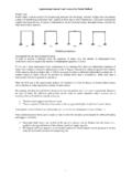
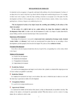
5 The structure is classified as statically unstable, determinate or indeterminate depending on whether dosi is 0, = 0 or 0. Table 1 shows the conditions of static Stability and Determinacy of 2D and 3D trusses and frames. Table 1: Statical Stability and Determinacy of Trusses and Frames structure Unknown Forces for Equations at Stability Dosi Member Reaction Joint Internal Hinge Reaction Dosi 2D Truss m r 2j * r 3 Dosi 0 m + r 2j 2D Frame 3m r 3j h r 3 + h 3m + r 3j h 3D Truss m r 3j * r 6 m + r 3j 3D Frame 6m r 6j h r 6 + h 6m + r 6j h 2 Problems on Structural Stability and Determinacy Determine the static/geometric Stability and statical indeterminacy of the following structures.
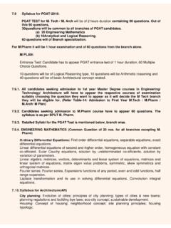
6 1. 2. 3. 4. 5. 6. 7. 8. 9. 10. 11. 12. 13. 14. 15. 16. 3 Axial Force, Shear Force and Bending Moment Diagram of Frames Frame is an assembly of several flexural members oriented in different directions and connected by rigid joints. Therefore, the axial force, shear force and bending moment diagrams of frame consist of drawing the individual AFD, SFD and BMD for each member (similar to beams) and assembling the diagrams for entire the frame, using the free-body diagram of each member.
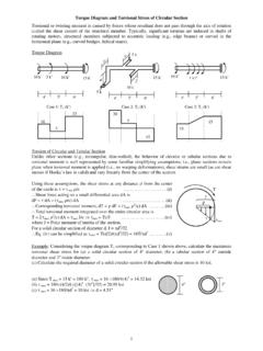
7 The equilibrium ( , Fx = 0, Fy = 0, Mz = 0) of each joint must be considered while drawing the member free-bodies. Example Draw the axial force, shear force and bending moment diagrams of the frames loaded as shown below. (i) (ii) Solution (i) For this frame, dosi = 3 3 + 3 3 4 = 0; , It is statically determinate Fx = 0 10 + HA 5 = 0 HA = 5 k MA = 0 10 10 VD 15 = 0 VD = k Fy = 0 VA + VD = 0 VA = k Reactions AFD (k) SFD (k) BMD (k-ft) (ii) dosi = 3 6 + 6 3 7 3 = 0; , It is statically determinate BMF = 0 HA 5 + MA = 0 MA = 5HA; Similarly BME = 0 MD = 5HD BMG = 0 HA 10 + VA + MA = 0 5HA 10 HA + = 0 HA = And also HD 10 VD + MD = 0 5HD 10 HD = 0 HD = Fy = 0 VA + VD = 0 VD = VA and Fx = 0 HA + HD + 10 = 0 = 10 3VA = 10 VA = k VD = VA = k HA = = 5 k and HD = = 5 k Reactions AFD (k) SFD (k) BMD (k-ft) 5 10 k 25 k-ft k k 5 k 5 k 10 k 5 5 50 50 D A 25 k-ft k k 5 k 5 k 5 5 5 25 25 25 25 MD VD HD G C B 10 k E F 5 MA VA HA D C B A 10 k 15 10 5 k 4 (iii) dosi = 3 3 + 6 3 4 = 3.
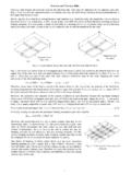
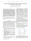
8 Assume internal hinges at E, F, G Free-body of Member EF YE = YF = 1 16/2 = 8 k Member FCG YG = YF + 1 2 = 10 k, XG = XF, and YF 2 1 2 2/2 + XF 8 = 0 XF = k XG = XF = k Member GD YD = YG = 10 k, XD = XG = k, and MD + XG 4 = 0 MD = 9 k-ft Overall Fx = 0 XA + XD = 0 XA = k, Fy = 0 YA = 1 20 10 = 10 k, and MA = 0 MA MD = 0 MA = 9 k-ft Member EF Member FCG Member GD Entire Frame 10 MA YD YA XA MD 1 k/ D B A G E F YE YF XE XF 2 2 16 1 k/ XF YF XG YG YD XG YG XD MD 4 1 k/ XD SFD (k) 10 C 8 18 9 10 18 9 32 BMD (k-ft) AFD (k) 10 5 Axial Force, Shear Force and Bending Moment Diagram of Multi-Storied Frames Example Draw the axial force, shear force and bending moment diagrams of the three-storied frame loaded as shown below, assuming (i) equal share of story shear forces between columns, (ii) internal hinge at column midspans.
9 Example Draw the AFD, SFD and BMD of the three-storied, two-bay frame loaded as shown below, assuming (i) internal hinge at the midspan of each column and beam, (ii) no axial force at middle columns. -4 C A 80 30 15 15 12k 8k 4k 12 2@10 =20 Column SFD (k) Beam BMD (k-ft) Beam SFD (k) Column AFD (k) 122 -4 4 12 10 6 m = 9, r = 6, j = 8 dosi = 3 9 + 6 3 8 = 9 Nine assumptions needed for statical Determinacy Equal shear among story columns VEG = VFH = 12/2 = 6k, VCE = VDF = (12 + 8)/2 = 20/2 = 10k VAC = VBD = (12 + 8 + 4)/2 = 24/2 = 12k End bending moments in columns are MEG = MFH = 6 10/2 = 30k , MCE = MDF = 10 10/2 = 50k MAC = MBD = 12 12/2 = 72k G E D B H F C A G E D H F B The rest of the calculations follow from the free-body diagrams Column BMD (k-ft) 72 50 30 72 50 30 Beam AFD (k)
10 -6 -4 -2 12 10 6 D A 20 20 12k 8k 4k 12 2@10 =20 m = 15, r = 9, j = 12 dosi = 3 15 + 9 3 12 = 18 18 assumptions needed for statical Determinacy Internal hinges BM = 0, at midspan of 6 beams and 9 columns No axial force at mid columns XBE = XEH = XHK = 0 J G E B K H F L I C The rest of the calculations follow from the free-body diagrams 6 Problems on AFD, SFD, BMD of Frames 1. Draw the AFD, SFD and BMD of the beam bcd in the frame abcde loaded as shown below. 2. Determine the degree of statical indeterminacy (dosi) of the frame abcd shown below. Also draw the Axial Force, Shear Force and Bending Moment diagram of the member ab, assuming the horizontal reactions at support a and d are equal.