Transcription of Structural Steel 1 of 18 Rev PLATE GIRDER Design …
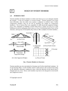
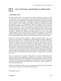
1 PLATE GIRDERS - II Job No: Sheet 1 of 18 Rev Job Title: PLATE GIRDER Worked Example - 1 Made by SSSR Date 15-04-00 Structural Steel Design Project Calculation Sheet Checked by PU Date 25-04-00 PROBLEM: The GIRDER showed in Fig. E1 is fully restrained against lateral buckling throughout its span. The span is 36 m and carries two concentrated loads as shown in Fig. E1. Design a PLATE GIRDER . Yield stress of Steel , fy = 250 N/mm2 Material factor for Steel , m = Dead Load factor, fd = Imposed load factor, f = LOADING Dead load: Uniformly distributed load, wd = 20 kN/ m (Including self-weight) Concentrated load, W1d = 200 kN Concentrated load, W2d = 200 kN Live load: Uniformly distributed load, w = 35 kN/m Concentrated load, W1 = 400 kN Concentrated load, W2 = 400 kN Fig.
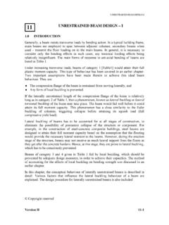
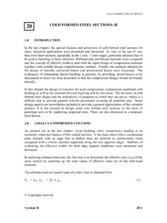
2 E1 Example PLATE GIRDER 36000 mmw W2 W1 18000 mm9000 mm 9000 mm Version II 16 - 12 PLATE GIRDERS - II Job No: Sheet 2 of 18 Rev Job Title: PLATE GIRDER Worked Example - 1 Made by SSSR Date 15-04-00 Structural Steel Design Project Calculation Sheet Checked by PU Date 25-04-00 Factored Loads: w = wd * fd + w * f = 20 * + 35 * = kN/m W 1 = W1d* fd + W1 * f = 200 * + 400 * = 870 kN W 2 = W2d * fd + W2 * f = 200 * + 400 * = 870 kN BENDING MOMENT AND SHEAR FORCE Bending moment (kN-m) Shear force (kN) UDL effect Concentrated load effect W = 870 TOTAL 20709 2301 The Design shear forces and bending moments are shown in Fig.
3 E2. INITIAL SIZING OF PLATE GIRDER Depth of the PLATE GIRDER : The recommended span/depth ratio for simply supported GIRDER varies between 12 for short span and 20 for long span GIRDER . Let us consider depth of the GIRDER as 2400 mm. Depth of 2400 mm is acceptable. 12879836*36* w143121= w78309*8704== Version II 16 - 13 PLATE GIRDERS - II Job No: Sheet 3 of 18 Rev Job Title: PLATE GIRDER Worked Example - 1 Made by SSSR Date 15-04-00 Structural Steel Design Project Calculation Sheet Checked by PU Date 25-04-00 (For drawing the bending moment and shear force diagrams, factored loads are considered) Fig.
4 E2 Bending moment and shear force diagrams kN/m 870 kN 870 kN 9000 mm 9000 mm 18000 mm36000 mm 2301 20709 2301 Shear force in kN Bending moment in kN-m Version II 16 - 14 PLATE GIRDERS - II Sheet 4 of 18 Rev Job Title: PLATE GIRDER Worked Example - 1 Made by SSSR Date 15-04-00 Structural Steel Design Project Calculation Sheet Checked by PU Date 25-04-00 Flange: py = 250 = N/mm2 Single flange area, By thumb rule, the flange width is assumed as times the depth of the section. Try 720 X 60 mm, giving an area = 43200 mm2. Web: Minimum web thickness for PLATE GIRDER in buildings usually varies between 10 mm to 20 mm.
5 Here, thickness is assumed as 14 mm. Hence, web size is 2400 X 14 mm SECTION CLASSIFICATION Flange: Hence, Flange is PLASTIC SECTION. *240010*20709mmpdMAyf=== <=== = == = =tBfyTbbVersion II 16 - 15 PLATE GIRDERS - II Job No: Sheet 5 of 18 Rev Job Title: PLATE GIRDER Worked Example - 1 Made by SSSR Date 15-04-00 Structural Steel Design Project Calculation Sheet Checked by PU Date 25-04-00 Web: Hence, the web is checked for shear buckling. CHECKS Check for serviceability: Web is adequate for serviceability. Check for flange buckling in to web: Assuming stiffener spacing, a > d Since, t (= 14 mm) > mm, the web is adequate to avoid flange buckling into the web.
6 Check for moment carrying capacity of the flanges: The moment is assumed to be resisted by flanges alone and the web resists shear only. Distance between centroid of flanges, hs = d + T = 2400 + 60 = 2460 mm Af = B * T = 720 * 60 = 43200 mm2 >==td250, > <== = Version II 16 - 16 PLATE GIRDERS - II Job No: Sheet 6 of 18 Rev Job Title: PLATE GIRDER Worked Example - 1 Made by SSSR Date 15-04-00 Structural Steel Design Project Calculation Sheet Checked by PU Date 25-04-00 Mc = pyf * Af * hs = * 43200 * 2460 * 10-6 = kN-m > 20709 kN-m Hence, the section in adequate for carrying moment and web is designed for shear.
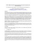
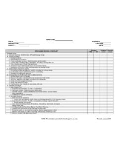
7 WEB Design The stiffeners are spaced as shown in Fig. E5. The spacing of stiffeners is taken as 3000 mm. The spacing can be increased towards the centre of the span for economy. Panel AB is the most critical panel (Maximum shear zone), so Design checks for the web are made for panel AB only. End panel ( AB) Design : d = 2400 mm t = 14 mm W2 Trial stiffener arrangement 12 panels @ 3000 mm [36000 mm]C D A B Version II 16 - 17 PLATE GIRDERS - II Job No: Sheet 7 of 18 Rev Job Title: PLATE GIRDER Worked Example - 1 Made by SSSR Date 15-04-00 Structural Steel Design Project Calculation Sheet Checked by PU Date 25-04-00 Calculation of critical shear strength, qcr.
8 Elastic critical stress, qe (when a/d > 1) = [ + (a/d)2][1000/(d/t)]2 = [1 + ( )2][1000/( )]2 = N/mm2 Slenderness parameter, w = [ (fyw/ m)/qe]1/2 = [ (250 ) ]1/2 = > Hence, Critical shear strength (qcr = qe) = N/mm2 Since, fv > qcr ( > ) Panel AB is designed using tension field action. Calculation of basic shear strength, qb: yb = (pyw2 3qcr2 + t2) 1/2 - t = ( 3* + ) 1/2 = 23 *240010*2301mmNdtFVAv===f() * += +=daqcrt ()222 +++= +++=Version II 16 - 18 PLATE GIRDERS - II Job No: Sheet 8 of 18 Rev Job Title: PLATE GIRDER Worked Example - 1 Made by SSSR Date 15-04-00 Structural Steel Design Project Calculation Sheet Checked by PU Date 25-04-00 Since, qb > fv ( > ) Panel AB is safe against shear buckling.
9 Checks for the web panel: End panel AB should also be checked as a beam (Spanning between the flanges of the GIRDER ) capable of resisting a shear force Rtf and a moment Mtf due to anchor forces. (In the following calculations boundary stiffeners are omitted for simplicity) Check for shear capacity of the end panel: Av = t .a = 14 * 3000 = 42000 mm2 Pv = pyw Av = * (250 ) * 42000/1000 = 5478 kN Since, Rtf < Pv, the end panel can carry the shear force. ) (* *14*2400* == =HHVersion II 16 - 19 PLATE GIRDERS - II Job No: Sheet 9 of 18 Rev Job Title: PLATE GIRDER Worked Example - 1 Made by SSSR Date 15-04-00 Structural Steel Design Project Calculation Sheet Checked by PU Date 25-04-00 Check for moment capacity of end panel AB: Since, Mtf < Mq ( < 4565) The end panel can carry the bending moment.
10 Design OF STIFFENERS Load bearing stiffener at A: Design should be made for compression force due to bearing and moment. Design force due to bearing, Fb = 2301 kN Force(Fm) due to moment Mtf, is Total compression = Fc = Fb + Fm = 2301 + 225 = 2526 kN mkNdHq === *2400*28143 Mtf1010mkNpyIMmmtaIayyq ========= 456510*) (*150010*315010*31503000*14*121121150023 0002674733kNaMFtfm22510* II 16 - 20 PLATE GIRDERS - II Job No: Sheet 10 of 18 Rev Job Title: PLATE GIRDER Worked Example - 1 Made by SSSR Date 15-04-00 Structural Steel Design Project Calculation Sheet Checked by PU Date 25-04-00 Area of stiffener in contact with the flange, A.