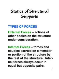
Transcription of Structural Steel Connections, Joints Details
1 6000 STEEL6000. STEEL6100& 6130 Design Data, Principles and Tools6100 & 6200 6140 Codes and Standards 6200 Material6300 6310 Members and Components 6320 Connections, Joints and Details dbl 6330 Frames and Assembles 6400 6410 AISC Specifications for Structural Joints6420 AISC303 CdfSt d dPti 6420 AISC 303 Code of Standard Practice 6430 AWS Structural Welding Code 6500 6510 NondestructiveTestingMethods6500 6510 Nondestructive Testing Methods 6520 AWS Structural Welding Code Tests6600 6610 SteelConstructionBMA Engineering, Inc. 600016600 6610 Steel Construction 6620/6630 NUREG 0800 / RG 6300. Design 6320. Structural Steel Connections, Joints and Details General Provisions (Section NJ1) TypesofStructuralWeldsandTheirApplicatio nsTypes of Structural Welds and Their Applications (Section NJ2 and AISC Manual Part 8) TypesofStructuralBoltsandBoltedConnectio ns Types of Structural Bolts and Bolted Connections (Section NJ3 and AISC Manual Part 7)(dl) AISC Connections (Section NJ and AISC Manual Part 9) HSS and Box Member Connections (Section NK) Selecting Standard Connections from the AISC Manual (AISC Manual Parts 9 & 10)() Seismic ConnectionBMA Engineering, Inc.
2 600026320. Structural Steel Connections, Joints and Details Mdl1 WldModule 1: WeldsThis section of the module covers: Introduction Basics of welding FilletweldFillet weld LRFD of welded connections Eccentricshearinwelds Eccentric shear in welds Welding problemsPrequalifiedwelds Prequalified weldsBMA Engineering, Inc. 60003 TypesofWeldsTypes of WeldsBMA Engineering, Inc. 60004 UsesofFilletWeldsUses of Fillet WeldsBMA Engineering, Inc. 60005 Complete and Partial Penetration Groove WeldsBMA Engineering, Inc. 60006 TypesofGrooveWeldsTypes of Groove WeldsBMA Engineering, Inc. 60007 PlugorSlotWeldPlug or Slot WeldBMA Engineering, Inc. 60008 StitchorSkipWeldStitch or Skip WeldBMA Engineering, Inc.
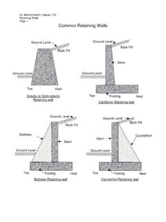
3 60009 BasicofWeldingBasic of Welding Structural welding is a process whereby the parts to be connected are heated and fused with a molten filler metal. Uponcoolingthestructuralsteel(parentmeta l)andUpon cooling, the Structural Steel (parent metal) and weld or filler metal will act as one continuous part. The fillermetalisdepositedfromaspecialelectr odeAfiller metal is deposited from a special electrode. A number of welding processes are used, depending on theapplicationthe application Field weldsShopwelds10 Shop weldsBMA Engineering, Inc. 6000 Welding Process and Metallurgyed gocessadeta u gyBMA Engineering, Inc. 600011 WeldingElectrodesWelding ElectrodesThe American Welding Society (AWS) has developed specifications for the filler metals to cover arc welding of the following steels:gg Carbon Alloy Alloy Stainless and corrosion resistingBMA Engineering, Inc.
4 600012 AWSE lectrodeClassificationAWS Electrode ClassificationAWS ELECTRODE CLASSIFICATION SYSTEMD igitSignificanceExample1st two orMinimum tensile strengthE-60xx = 60,000 psi (min)1st three2nd lastg( stress relieved )Welding position,p()E-110xx = 110,000 psi (min)Exx1x = all positions2nd lastWelding positionE-xx1x = all positionsE-xx2x = horizontal and flatE-xx3x = flatLastPower supply, type of slag,type of arc, amount ofpenetration, presence ofpenetration, presence of iron powder in coatingNOTE: Prefix E (toleftof4or5-digit number) signifies arc welding electrodeNOTE: Prefix E ( to left of 4 or 5digit number) signifies arc welding electrodeBMA Engineering, Inc. 600013 BasicofweldingBasic of weldingMinimumweldsizemaximumweldsizeand minimumlength:Minimum weld size, maximum weld size, and minimum length: The minimum size of a fillet weldis a function of the thickness of the thicker connected part.
5 See AISC Table pfor Details . The maximum size of a fillet weldis as follows: Along the edge of a connected part less than inch thick, the maximum fillet weld size (w) equals the plate thickness Forothervaluesofplatethicknesstthemaximu mweldsizeist 1/16inFor other values of plate thickness, t, the maximum weld size is t 1/16 Engineering, Inc. 6000 BasicofweldingBasic of welding The minimum permissible lengthof a fillet weld is 4 times its size. If only a shorter length is available, w = L/4. For the welds in the connectionshownbelowL Wtoaddressshearlaginsuchconnection shown below, L Wto address shear lag in such connections. When a weld extends to the corner of a member it must beWhen a weld extends to the corner of a member, it must be continued around the corner (an end return) Prevent stress concentrationsat the corner of the weld Minimum length of return is 2w15 BMA Engineering, Inc.
6 6000 Effective Area of WeldsBMA Engineering, Inc. 600016 FilletWeldFillet Weld The design and analysis of fillet welds is based on the assumption that the geometry of the weld is a 45 degree right triangleSt d dldidiit thfih Standard weld sizes are expressed in sixteenths of an inch. Failure of fillet welds is assumed to occur in shear on the Engineering, Inc. 6000 FilletWeldFillet Weld The critical shearing stress on a weld of length Lis given by f = P/( ) Ifthlti thitithlditdFthildi If the ultimate shearing stress in the weld is termed FW, the nominal design strength of the weld can be written as Rn= ( Fw)= ( [ ])= For E70XX and E80XX electrodes, the design stresses are Fw, or ksi and 36 ksi, respectively.
7 Inadditionthefactoredloadshearonthebasem etalshallnotproducea In addition, the factored load shear on the base metal shall not produce a stress in excess of FBM, where FBMis the nominal shear strength of the connected material. The factored load on the connection is thus subjected to hlfthe limit of Rn= FBMAg= ( )Ag= Engineering, Inc. 6000 Eccentric ShiShear in WeldsWelds19 BMA Engineering, Inc. 6000 Eccentric Shear in Welds Eccentricity in the plane of the faying surface Instantaneous center of rotation methodInstantaneous center of rotation method Elastic method Eccentricity normal to the plane of the faying surface20 BMA Engineering, Inc. 6000 WeldingProblemsWelding Problems Lamellar tears Weldshrinkageand Weld shrinkage andstructural distortion Residual stresses Fatigue sensitivityBMA Engineering, Inc.
8 600021 LamellarTearsLamellar TearsBMA Engineering, Inc. 600022 PrebendingforWeldShrinkagePre bending for Weld ShrinkageBMA Engineering, Inc. 600023 AISCS tandardConnectionsAISC Standard Connections and Suggested DetailsThis last section of the modulecovers the following: Prequalifiedwelds Prequalified welds Suggesteddetails Suggested Details BMA Engineering, Inc. 600024 Prequalified WeldsBMA Engineering, Inc. 600025 Prequalified Complete Penetration Groove WeldsBMA Engineering, Inc. 600026 Prequalified Complete Penetration Groove Welds (Cont d.)BMA Engineering, Inc. 600027 Prequalified Partial Penetration Groove WeldsBMA Engineering, Inc. 6300. Design 6320. Structural Steel Connections, Joints and Details Objective and Scope Metdlld Module 1: Welds Introduction Basics of welding Fillet weld LRFD of welded connections EccentricshearinweldsEccentric shear in weldsBMA Engineering, Inc.
9 6000296320. Structural Steel Connections, Joints and Details Mdl2 BltModule 2: BoltsThissectionofthemodulecovers:This section of the module covers: Introduction of Fastenersldfbl dh Failure modes of bolted shear connections LRFD Fasteners LRFD of slip critical connections Eccentric shear in bolts Fasteners in combined shear and tension DesignandErectionConcernsDesign and Erection Concerns Prequalified boltsBMA Engineering, Inc. 600030 BoltedConnectionsBolted ConnectionsBMA Engineering, Inc. 600031 RivetedConnectionsRiveted ConnectionsBMA Engineering, Inc. 600032 PinnedConnectionsPinned ConnectionsBMA Engineering, Inc. 600033 Properties of Structural BoltspMINIMUMASTM DESIGNATIONBOLT DIAMETER, in.
10 MINIMUMTENSILESTRENGTH,MINIMUMYIELDSTREN GTH,STRENGTH,ksiksi, lb tl1/4 t 460A307, low-carbon steel1/4 to 460_High-strengthStructural bolts: Structural bolts:A325, medium-carbon steel1/2 to 111/8 t 11/21201059281steelA490, alloy steel1-1/8 to 1-1/21/2 to 1- 1/210515081130 BMA Engineering, Inc. 600034 UnfinishedBolts(A307)Unfinished Bolts (A307) Made from low carbon Steel Minimum tensile strength of 60 ksi Least expensive Morearerequiredinaparticularconnection More are required in a particular connection Used in light structures Manufactured in grades A and B Induced tension is relatively small andunpredictableBMA Engineering, Inc. 600035 HighStrengthBolts(A325)High Strength Bolts (A325) Most commonly used high strength bolt Made of heat treated medium carbon Steel Tensile strength decreases as the diameterincreasesincreases Available in Types 1, 2, and 3 BMA Engineering, Inc.