Transcription of STRUCTURAL STEEL TERMS/ LAYOUT AND FABRICATION OF …
1 CHAPTER 3 STRUCTURAL STEEL TERMS/ LAYOUT ANDFABRICATION OF STEEL AND PIPES tructural STEEL is one of the basic materials usedin the construction of frames for most industrialbuildings, bridges, and advanced base , you, as a Seabee Steelworker, must have athorough knowledge of various STEEL structuralmembers. Additionally, it is necessary before anystructural STEEL is fabricated or erected, a plan of actionand sequence of events be set up. The plans,sequences, and required materials are predeterminedby the engineering section of a unit and are then drawnup as a set of blueprints. This chapter describes theterminology applied to STRUCTURAL STEEL members, theuse of these members, the methods by which they areconnected, and the basic sequence of events whichoccurs during STEEL MEMBERSYour work will require the use of variousstructural members made up of standard structuralshapes manufactured in a wide variety of shapes ofcross sections and sizes.
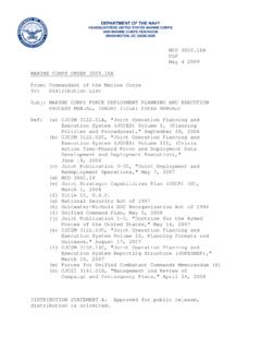
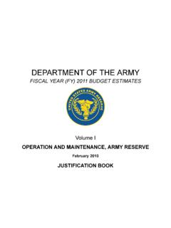
2 Figure 3-1 shows many ofthese various shapes. The three most common typesof STRUCTURAL members are the W-shape (wide flange),the S-shape (American Standard I-beam), and theC-shape (American Standard channel). These threetypes are identified by the nominal depth, in inches,along the web and the weight per foot of length, inpounds. As an example, a W 12 x 27 indicates aW-shape (wide flange) with a web 12 inches deep anda weight of 27 pounds per linear foot. Figure 3-2shows the cross-sectional views of the W-, S-, andC-shapes. The difference between the W-shape andFigure 3-1. STRUCTURAL shapes and 3-2. STRUCTURAL S-shape is in the design of the inner surfaces of theflange. The W-shape has parallel inner and outerflange surfaces with a constant thickness, while theS-shape has a slope of approximately 17 on the innerflange surfaces. The C-shape is similar to the S-shapein that its inner flange surface is also slopedapproximately 17.
3 The W-SHAPE is a STRUCTURAL member whosecross section forms the letter H and is the most widelyused STRUCTURAL member. It is designed so that itsflanges provide strength in a horizontal plane, whilethe web gives strength in a vertical plane. W-shapesare used as beams, columns, truss members, and inother load-bearing BEARING PILE (HP-shape) is almostidentical to the W-shape. The only difference is thatthe flange thickness and web thickness of the bearingpile are equal, whereas the W-shape has different weband flange S-SHAPE (American Standard I-beam) isdistinguished by its cross section being shaped like theletter I. S-shapes are used less frequently thanW-shapes since the S-shapes possess less strength andare less adaptable than C-SHAPE (American Standard channel) hasa cross section somewhat similar to the letter C. It isespecially useful in locations where a single flat facewithout outstanding flanges on one side is C-shape is not very efficient for a beam or columnwhen used alone.
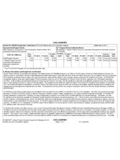
4 However, efficient built-upmembers may be constructed of channels assembledtogether with other STRUCTURAL shapes and connected byrivets or ANGLE is a STRUCTURAL shape whose crosssection resembles the letter L. Two types, as illustratedin figure 3-3, are commonly used: an equal-leg angleand an unequal-leg angle. The angle is identified bythe dimension and thickness of its legs; for example,angle 6 inches x 4 inches x 1/2 inch. The dimensionof the legs should be obtained by measuring along theoutside of the backs of the legs. When an angle hasunequal legs, the dimension of the wider leg is givenfirst, as in the example just cited. The third dimensionapplies to the thickness of the legs, which al ways haveequal thickness. Angles may be used in combinationsof two or four to form main members. A single anglemay also be used to connect main parts PLATE is a STRUCTURAL shape whose crosssection is in the form of a flat rectangle.
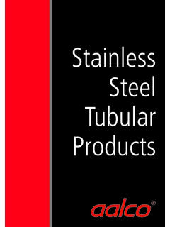
5 Generally, amain point to remember about plate is that it has awidth of greater than 8 inches and a thickness of 1/4inch or are generally used as connections betweenother STRUCTURAL members or as component parts ofbuilt-up STRUCTURAL members. Plates cut to specificsizes may be obtained in widths ranging from 8 inchesto 120 inches or more, and in various thicknesses. Theedges of these plates may be cut by shears (shearedplates) or be rolled square (universal mill plates).Plates frequently are referred to by their thicknessand width in inches, as plate 1/2 inch x 24 inches. Thelength in all cases is given in inches. Note in figure 3-4that 1 cubic foot of STEEL weighs 490 pounds. hisweight divided by 12 gives you , which is theweight (in pounds) of a STEEL plate 1 foot square and 1inch thick The fractional portion is normally droppedand 1-inch plate is called a 40-pound plate. In practice,you may hear plate referred to by its approximateweight per square foot for a specified thickness.
6 Anexample is 20-pound plate, which indicates a 1/2-inchplate. (See figure 3-4.)The designations generally used for flat STEEL havebeen established by the American Iron and SteelInstitute (AISI). Flat STEEL is designated as bar, strip,Figure 3-3. 3-4. Weight and thickness of STEEL , or plate, according to the thickness of thematerial, the width of the material, and (to someextent) the rolling process to which it was 3-1 shows the designations usually used forhot-rolled carbon steels. These terms are somewhatflexible and in some cases may STRUCTURAL shape referred to as a BAR has awidth of 8 inches or less and a thickness greater than3/16 of an inch. The edges of bars usually are rolledsquare, like universal mill plates. The dimensions areexpressed in a similar manner as that for plates; forinstance, bar 6 inches x 1/2 inch. Bars are available ina variety of cross-sectional shapes round,hexagonal, octagonal, square, and flat.
7 Three differentshapes are illustrated in figure 3-5. Both squares androunds are commonly used as bracing members oflight structures. Their dimensions, in inches, apply tothe side of the square or the diameter of the that you have been introduced to the variousstructural members used in STEEL construction, let usdevelop a theoretical building frame from where you,the Steelworker, would start on a project after all theearthwork and footings or slab have been this sequence is theoretical and may varyFigure 3-5. , depending on the type of structure BOLTSA nchor bolts (fig. 3-6) are cast into the concretefoundation. They are designed to hold the columnbearing plates, which are the first members of a steelframe placed into position. These anchor bolts mustbe positioned very carefully so that the bearing plateswill be lined up PLATESThe column bearing plates are STEEL plates ofvarious thicknesses in which holes have been eitherdrilled or cut with an oxygas torch to receive theFigure 3-6.
8 Anchor 3-1. Plate, Bar, Strip, and Sheet designation3-3anchor bolts (fig. 3-7). The holes should be slightlylarger than the bolts so that some lateral adjustment ofthe bearing plate is possible. The angle connections,by which the columns are attached to the bearingplates, are bolted or welded in place according to thesize of the column, as shown in figure the bearing plate has been placed intoposition, shim packs are set under the four comers ofeach bearing plate as each is installed over the anchorbolts, as shown in figure 3-9. The shim packs are 3- to4-inch metal squares of a thickness ranging from 1 1/6to 3/4 inch, which are used to bring all the bearingFigure 3-7. Column bearing 3-8. Typical column to baseplate 3-9. Leveled bearing to the correct level and to level each bearingplate on its own bearing plates are first leveled individually byadjusting the thickness of the shim packs.
9 Thisoperation may be accomplished by using a 2-foot levelaround the top of the bearing plate perimeter anddiagonally across the bearing completion of the leveling operation, allbearing plates must be brought either up to or down tothe grade level required by the structure being erectedAll bearing plates must be lined up in all directionswith each other. This may be accomplished by usinga surveying instrument called a builder s level. Stringlines may be set up along the edges and tops of thebearing plates by spanning the bearing plates aroundthe perimeter of the structure, making a grid networkof string lines connecting all the bearing all the bearing plates have been set andaligned, the space between the bearing plate and thetop of the concrete footing or slab must be filled witha hard, nonshrinking, compact substance calledGROUT. (See fig. 3-9.) When the grout has hardenedthe next step is the erection of the flange members, as nearly square in crosssection as possible, are most often used for diameter pipe is also used frequentl y (fig.)
10 3-10),even though pipe columns often present connectingdifficulties when you are attaching other may also be fabricated by welding or boltinga number of other rolled shapes, usually angles andplates, as shown in figure the structure is more than one story high, it maybe necessary to splice one column member on top ofanother. If this is required, column lengths should be3-4 Figure 3-10. Girder span on pipe 3-11. Built-up column that the joints or splices are 1 1/2 to 2 feet abovethe second and succeeding story levels. This willensure that the splice connections are situated wellabove the girder or beam connections so that they donot interfere with other second story splices are joined together by spliceplates which are bolted, riveted, or welded to thecolumn flanges, or in special cases, to the webs as the members are the same size , it is common practiceto butt one end directly to the other and fasten thesplice plates over the joint, as illustrated infigure 3-12.