Transcription of Structured Annotations for 2D-to-3D Modeling
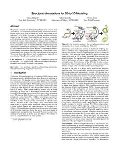
1 Structured Annotations for 2D-to-3D ModelingYotam Gingold (New York University / JST ERATO)Takeo Igarashi (University of Tokyo / JST ERATO)Denis Zorin (New York University)1In this talk, Structured Annotations for 2D-to-3D Modeling , I will present an interface for quickly turning 2D drawings into undetailed 3D is joint work with Takeo Igarashi and Denis and Paper Sketches2 This work is motivated by the observation that 2d drawing remains easier than 3d modeling for experts and novices alike. Even experts create 2D concept artwork prior to any 3d modeling , yet they have no direct way of --- but desire to --- use (using) them during the 3d modeling process.
2 Unfortunately, automatic approaches are far from being able to interpret arbitrary 2D drawings , which are often inconsistent (containing multiple perspectives), inaccurate, and Expert Systems[Maya][Mudbox][Thorm len and Seidel 2008]Concept artwork plays no direct role3In traditional, professional 3d modeling tools, concept artwork plays no direct role. At most, designers will draw axis-aligned sketches, and place them in the 3D scene for reference. [Tsang et al. 2004] and [Thorm len and Seidel 2008] introduced techniques based on axis-aligned Systems ( )Teddy [Igarashi et al.]
3 1999]ShapeShop[Schmidt et al. 2005-8]See [Olsen et al. 2008] for a recent [Nealen et al. 2007]Spore [Maxis 2008]Can t trace a guide image4 There are a variety of novice systems, as well. These systems make it possible for novices to create 3D models, and they make Modeling easier for experts, as well. Sketch-Based Modeling is a popular approach for creating free-form models. In this approach, users typically sketch silhouette curves from different views. This leverages users' 2d drawing skills. However, the view matters --- it determines the sketched stroke s plane --- so users must rotate to a good view before every stroke.
4 As a result, the workflow takes the form of Sketch-Rotate-Sketch. In our evaluations, we found that this constant rotation is difficult for novice users. (An evaluation of a pure 3D manipulation task in [Schmidt et al. 2008] reached a similar conclusion.) If you re not working from a guide image and the shape is entirely in your head, then this workflow is a good one (novice rotation difficulties notwithstanding). Otherwise, sketching the shape from novel views makes it difficult to model from a guide image. Examples of this approach include Teddy, FiberMesh, and brings us to our approach, which is most similar in spirit to the Single-View Modeling approaches of [Zhang et al.]
5 2001] and [Wu et al. 2007]. We want to allow users to model from guide images, such as these. The idea is to leverage the user s interpretive abilities to describe the shape.<click>The user does this by placing shape primitives and Annotations that look like this. The primitives convey local shape information, and the Annotations specify geometric relationships, such as same lengths and angles, symmetries, and attachments.<click>The 3D model is created from these primitives and Annotations ; we don t consult the guide that in this interpretive process, we do not expect that users have a consistent 3D mental model of the shape; we aim to create plausible, reasonable quality 3D models from a user's possibly inconsistent user does this by placing shape primitives and Annotations that look like this.
6 The primitives convey local shape information, and the Annotations specify geometric relationships, such as same lengths and angles, symmetries, and attachments.<click>The result is these 3D models created from the primitives and Annotations ; we don t consult the guide that in this interpretive process, we do not expect that users have a consistent 3D mental model of the shape; we aim to create plausible, reasonable quality 3D models from a user's possibly inconsistent result is these 3D models created from the primitives and Annotations ; we don t consult the guide that in this interpretive process, we do not expect that users have a consistent 3D mental model of the shape.
7 We aim to create plausible, reasonable quality 3D models from a user's possibly inconsistent & 2 User StudiesImplementation DetailsConclusion8In this talk, I will present our interface, results, and two user studies before discussing implementation [Vilppu 1997][Blair 1994] 2d drawing Approaches9 The inspiration for our approach comes from 2d drawing approaches, which are based on composing a model out of primitive shapes --- or decomposing, if drawing reality. In our approach, we reconcile the primitives' local shape information with the semantic information from Annotations to create a plausible, globally consistent 3D poor quality drawings are understandable by humans, and are able to convey local shape information, as well as semantic information about a Cylinders & Ellipsoids10<video> In our interface, the user loads an image and proceeds to place 2D primitives primitives are generalized cylinders and editing operations are performed in the 2D view on the left.
8 The view on the right displays the resulting 3D Cylinders & Ellipsoids10<video> In our interface, the user loads an image and proceeds to place 2D primitives primitives are generalized cylinders and editing operations are performed in the 2D view on the left; the view on the right displays the resulting 3D CylinderEllipsoid11 Users manipulate these primitives with a variety of are the generalized cylinder s : Generalized Cylinder12<video> <demo> A generalized cylinder is created with a spine stroke. Its cross sections can be tilted out of the view plane.
9 Cross sections' radii can be adjusted, as well. There are handles to provide control over its end caps. The cylinder's generalized symmetry plane, called its symmetry sheet, can also be adjusted. This affects symmetry-related Annotations , which we ll see shortly. The user can also draw or choose a non-circular cross section at any point along the spine. Finally, users can oversketch or drag to deform the : Generalized Cylinder12<video> <demo> A generalized cylinder is created with a spine stroke. Its cross sections can be tilted out of the view plane.
10 Cross sections' radii can be adjusted, as well. There are handles to provide control over its end caps. The cylinder's generalized symmetry plane, called its symmetry sheet, can also be adjusted. This affects symmetry-related Annotations , which we ll see shortly. The user can also draw or choose a non-circular cross section at any point along the spine. Finally, users can oversketch or drag to deform the : Ellipsoid13<video> <demo> An ellipsoid is created by drawing its silhouette. Ellipsoids have handles for tilting the long axis out of the view plane, and for controlling the radius of the two shorter axes.


