Transcription of Student CNC Guide - KTH
1 Student CNC Guide KTH Royal Institute of Technology Viktor Stenberg Stockholm, Sweden, 2015-12-07 Student CNC Guide Viktor Stenberg KTH Royal Institute of Technology i Table of Contents Table of Contents .. i Introduction .. ii CNC Machining Safety .. 1 Technical Glossary .. 2 What is a CNC Milling Machine? .. 3 Intro .. 3 Coordinate Systems .. 5 Absolute Coordinate System .. 6 Work Coordinate System .. 7 G - Code Programming Language .. 8 Tools .. 9 Fixtures .. 12 Machine Overview .. 14 The CNC Mill .. 14 Tools and Toolholders .. 19 Accessories .. 23 Mach 3 Overview .. 25 Intro .. 25 Jogging .. 30 Setup Work Coordinate System Origin .. 30 MDI Overview .. 31 Wizards Overview .. 31 Using the Auto Tool Zero Probe .. 31 Using the Touch Probe .. 32 CAD/CAM Software Overview .. 34 Intro .. 34 autodesk Fusion 360 .. 34 autodesk Fusion 360 Design Workflow .. 35 Workflow of Machining a Part.
2 39 Speeds and Feeds Table .. 43 Prefix Reference .. 45 G - Code Reference .. 46 M - Code Reference .. 47 Student CNC Guide Viktor Stenberg KTH Royal Institute of Technology ii Introduction This manual aims to quickly make you successful in operating the Student CNC Mill and making very precise and high quality parts for your project. The first sections of the manual takes you through the very basics of what a CNC Mill is and what operations it can do, the basics of how the machine works, what G - Code is, the different types of tools that can be used and other practical things you need to know. This is followed by an overview of the actual Student CNC Mill. Clear diagrams with key components is marked out and explained. The available accessories and tools are reviewed. Next the control software is explained, how it works and the minimum features needed to know. This is followed by a quick introduction of the CAD/CAM software.
3 Then the workflow of designing a part in autodesk Fusion 360 and generate the G - Code for the CNC Mill is presented. Now that the fundamentals of the CNC process has been explained, a step by step section is presented which shows all of all the steps needed to perform in order to go from drawing to finished part. A number of useful tables can also be found in the manual. I hope that the manual enables you to succeed in operating the CNC Mill! Sincerely, Viktor Stenberg Author of Student CNC GuideStudent CNC Guide Viktor Stenberg KTH Royal Institute of Technology 1 CNC Machining Safety When a CNC machine is operated properly, using the machine is a relative safe process. This is only under the circumstances that the following rules are followed! Safety Rules 1. Do not operate the machine if you are not sure of what you are doing, call for help by some who can! 2. Always wear safety glasses when you are near the machine!
4 A broken cutter / chip / material can shoot out of the machine during operation. 3. Always make sure that the spindle is tightened! A loose tool will cause vibrations and can be shoot away during cutting. 4. Make sure the stock material is properly tightened! The material need to be firmly secured to the table. 5. Hit the Emergency Stop / Escape Key if something goes wrong! This quickly stops the machine preventing danger. 6. Never put your Fingers / Hand / Head near the spinning cutter! Don't risk your fingers, stop the machine by Feedhold, adjust then resume. 7. Never leave the machine unattended! If something goes wrong, you need to be around to stop the machine. Student CNC Guide Viktor Stenberg KTH Royal Institute of Technology 2 Technical Glossary Stock Material The raw material the part should be machined out of. G - Code The programming language of the CNC Mill.
5 Feedrate The speed of the axis. CAD Software to draw parts in 3D. CAM Software to generate G - Code from the CAD files. MDI Manual G -Code input in controlling software (Mach 3). DRO Digital Read Out. Displays a number, typically an axis coordinates value. Student CNC Guide Viktor Stenberg KTH Royal Institute of Technology 3 What is a CNC Milling Machine? Intro A CNC Milling machine is a computer controlled machine that can be used to make very precise parts. The machine works by removing material from the workpiece with a rotating cutting tool. The machine does this by guiding the tool in all three directions of the cartesian coordinate system, that meaning along the X, Y and Z axis. The arrows in the figure below illustrate the three directions the CNC Mill can move in. Figure 1: Illustration of a CNC Mill Student CNC Guide Viktor Stenberg KTH Royal Institute of Technology 4 The CNC Mill can machine many different materials, examples are steel, aluminum, brass, copper and plastic.
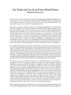
6 A Mill is not designed for cutting wood and should not be used for that. Examples of operations that can be made in a CNC Mill is to cut a profile shape, engrave text, mill a 3D surface, drill holes and mill bearing pockets. Fig 2: Example of CNC Milling Fig 3: Example of CNC Milled parts Student CNC Guide Viktor Stenberg KTH Royal Institute of Technology 5 Coordinate Systems The CNC Mill can as previously mentioned move in the X, Y and Z directions of the cartesian coordinate system. The coordinate system is defined as illustrated below. Figure 4: Coordinate system Note that the coordinate system is defined relative to the tool motion! This means that when the machine for example is cutting in the positive X direction, the tool should move to the right which is the positive direction as defined by the coordinate icon in Fig 4. Since the tool cannot move in any other direction then up and down due to the design of the mill, the table has to move.
7 The table and the stock attached to it will thus have to travel in the opposite direction, to the left when the mill is cutting in the positive X direction in order for the relative motion to be to the right. The same logic applies to the Y axis, but not the Z axis. Z+ Y+ X+ Student CNC Guide Viktor Stenberg KTH Royal Institute of Technology 6 Absolute Coordinate System The absolute coordinate system of the CNC Mill is called the Machine Coordinate System, and its Origin is located at the endpoint of the three axis's. From the machine origin the X and Y axis can only move in the positive direction and the Z axis can only move in the negative direction. The origin of the machine coordinate system is called Home Position. Every time the machine starts up the operator should perform a homing cycle to find the Home Position. This enables the machine to know where it is. The machine finds the Home Position by slowly driving each axis to their extreme limit (-X, -Y, +Z).
8 As each axis reaches its mechanical limit, a sensor triggers and stops the motion. When this has been done to all three axes, the position of the machine is at the origin of the machine coordinate system. It is very important that the machine is referenced to its absolute position since the control computer and G - Code programs base some movements with respect to this coordinate system. Safe axis limits are also based on this coordinate system. The operator must perform a Homing Cycle on every startup of the machine! Figure 5 illustrates the origin / home position of the machine coordinate system. Fig 5: Machine Coordinates origin Student CNC Guide Viktor Stenberg KTH Royal Institute of Technology 7 Work Coordinate System When programming the CNC Mill it is useful to define a custom coordinate system that can be set anywhere on the part to be milled. A Work Coordinate System can be setup by moving the machine so that the cutter is in the appropriate place and call this the origin of the Work Coordinate System The origin of the Work Coordinate System will typically be set at the center of the part and with the tip of the cutter directly above the part.
9 Figure 6: Work Coordinate System Student CNC Guide Viktor Stenberg KTH Royal Institute of Technology 8 G - Code Programming Language So how do you make the machine move and actually machine a part? This is done by running a CNC program. A CNC program is loaded into the Control Computer, which then is executed causing the machine to perform the movements programmed in the file. The G - Code Programming Language is the name of the language that the CNC machine can understand and convert into actual motion of the machine. The Control Computer reads the G - Code file line by line and commands the machine to do the movements. The language consists of a set of codes called G - Codes and M - Codes, each instruction have a specific function, for example to command a motion from one point to another. The following is an example of a G - Code program: ; Example program G54 ; Use G54 work coordinates offset G90 ; Absolute positioning G0 X0 Y0 Z0 ; Rapid move to (0,0,0) G1 Z-1 F50 ; Lower the tool to Z = -1 at a speed of 50 mm/min G1 X30 Y30 F100 ; Move to X = Y = 30 mm simultaneously, 100 mm/min M30 ; End of program The G - Code program can be written manually in a file that then is executed, or inputted line by line and executed in real time through the MDI input of the Control Computer.
10 These methods are useful if some very simple operations are to be made. It's much more common to use a CAM Software to generate the G - Code. The CAM software imports a 2D or 3D model and generates a G - Code file to cut the part. There is also a simpler type of CAM software called Wizards that will generate G - Code for common operations like milling a circular pocket or drilling a hole. Wizards are very handy if a relatively simple part with few operations are to be made. These can be found in the CNC Software and do not need a CAD model. A complete list of all the programming codes can be found under the sections 'G - Code Reference', 'M - Code Reference' and 'Prefix Reference'. Student CNC Guide Viktor Stenberg KTH Royal Institute of Technology 9 Tools The CNC machine uses different tools to perform various operations on the part. The following list describes some common tools.