Transcription of Styles 741 and 743 Vic-Flange Adapters
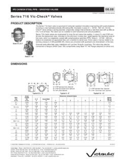
1 R IPS CARBON STEEL PIPE grooved COUPLINGS victaulic IS AN ISO 9001 CERTIFIED COMPANY REGISTERED TRADEMARK OF victaulic COPYRIGHT 2002 victaulic PRINTED IN REV D victaulic Company of America Phone: 1-800-PICK-VIC (1-800-742-5842) Fax: 610-250-8817 Company of Canada Phone: 905-884-7444 Fax: 905-884-9774 e-mail: Europe Phone:32-9-381-1500 Fax: 32-9-380-4438 e-mail: America Latina Phone: 610-559-3300 Fax: 610-559-3608 e-mail: Asia Pacific Phone: 65-6235-3035 Fax: 65-6235-0535 e-mail: Styles 741 and 743 Vic-Flange Adapters PRODUCT DESCRIPTION Style 741 Style 741 Vic-Flange adapter is designed for directly incorporating flanged components with ANSI CL. 125 or CL. 150 bolt hole patterns into a grooved pipe system.
2 Sizes 2 - 12" (50 - 300 mm) are hinged for easy handling with integral end tabs which facilitate assembly. Sizes 14 - 24" (350 - 600 mm) are cast in four (4) identical segments which are interconnected as assembly is design incorporates small teeth inside the key shoulder to prevent rotation. These teeth should be removed when Vic-Flange adapter is utilized with a victaulic Series 700 grooved end butterfly valve, Schedule 5 pipe or plastic Adapters may only be used on Vic-300 butterfly valves on one side in 2 - 8" (50 - 200 mm) sizes. They are not recommended for 10 and 12" (250 and 300 mm) adapter Style 741 is not recommended for use with victaulic Series 709 butterfly valves (contact victaulic for recommendations). They may only be used on one side of victaulic Series 700 butterfly valve, sizes 2 - 4" (50 - 100 mm) fitted with standard or lever-lock handles.
3 Vic-Flange adapter must be assembled so it does not interfere with handle operation. Style 743 Vic-Flange Style 743 flange-to-groove adapter permits direct connection of ANSI Class 300 flanged components into a grooved system. The two-piece, hinged housing engages into the pipe groove and bolts directly to any standard flanged component. The conventional bolt hole pattern allows for easy, fast assembly. Style 743 rotates 360 for proper alignment of bolt holes before tightening. Vic-Flange gaskets utilize the victaulic pressure-responsive design, sealing on the pipe end and directly to the opposing flange face. No standard flange gasket is 743 is designed to mate with raised-face flanges, but can be used with flat-face flanges by removing the raised projections on the outside face of the Request Victaulicpublication for for ClarityStyle 7412 - 12" SizesFMRequest Victaulicpublication for 74114 - 24" SizesULCFMUL Request Victaulicpublication for 743 Illustrations exaggerated for clarityVic-Flange NotesBecause of the outside flange dimension, Vic-Flange should not be used within 90 of one another on a standard fitting.
4 When wafer or lug-type valves are used adjoining a victaulic fitting, check disc dimensions to assure proper Adapters should not be used as anchor points for tie-rods across non-restrained joints. Mating rubber faced flanges, valves, etc., requires the use of a Vic-Flange gaskets must always be assembled with the color coded lip on the pipe and the other lip facing the mating flange. 2 Styles 741 and 743 Vic-Flange Adapters DIMENSIONS Style 741 Sizes 2 - 12" (50 - 300 mm) ANSI Class 125 and 150 FlangeNote: Gray area of mating face must be free from gouges, undulations ordeformities of any type for for Clarity Pipe * * d. Bolt SizeInchesSealing SurfaceInches/ A Max. B ,3304 5 / 8 X 2 3 / 4 5060,3206559206087172152121191,4 2 1 / 2 ,9504 5 / 8 X 6573,0206586807399200178140222,1 ,8854 5 / 8 X 8088,920651284089115214191152242,4 ,7708 5 / 8 X 100114,3206521225114141252229191243,4 ,2908 3 / 4 X 3 1 / 2 125141,3206532440141171279254216253,9 ,3508 3 / 4 X 3 1 / 2 150168,3206546060168198305279241254,5 165,1 ,9608 3 / 4 X 3 1 / 2 + 165,1206544320165195279241254,5 ,5008 3 / 4 X 3 1 / 2 200219,1206577875219252372343298297,5 ,21512 7 / 8 X 250273,020651211102733134374063623011,0 ,28512 7 / 8 X 300323,920651702703243645144834323221,2 *Refer to notes on page 4.
5 + W dimension does not apply. Total bolts required to be supplied by installer, may be ordered from NOTES: Style 741 Vic-Flange Adapters provide rigid joints when used on pipe with standard cut or roll groove dimensions and consequently allow no linear or angular movement at the joint. When used with victaulic Series 700 butterfly valves, plastic pipe or light wall metallic pipe, small teeth in of key section should be removed and may be used on one side of the valve. Contact victaulic for information on AS2129 - Table E; ISO 2084 (PN10); DIN 2532 (PN10) and JIS B-2210 (10K) flanges. Style 741 Sizes 14 - 24" (350 - 600 mm) ANSI Class 125 and 150 Flanges Pipe * *NAssembly Bolts Draw Bolts SealingSurfaceInches/ A Max. B ,180121 X 4 1 / 2 4 5 / 8 X 3 1 / 2 350355,620652055003564164952262253347637 28,1 ,300161 X 4 1 / 2 4 5 / 8 X 3 1 / 2 400406,420652683354064675522268959754037 35,8 ,340161 1 / 8 X 4 3 / 4 4 3 / 4 X 4 1 / 4 450457,020653397004575085722673764857840 37,3 ,250201 1 / 8 X 5 1 / 4 4 3 / 4 X 4 1 / 4 500508,020654194005085726413080069963543 46,9 ,700201 1 / 4 X 5 3 / 4 4 3 / 4 X 4 1 / 4 600610,020656038656107057433591481374949 64,4 *Refer to notes on page 4.
6 Total bolts required to be supplied by installer, may be ordered from victaulic . Bolt sizes for conventional flange-to-flange connection. Longer bolts required when Vic-Flange utilized with wafer-type valves. Draw bolts supplied with 14 - 24" (350 - 600 mm) Vic-Flange for ClarityNote: Gray area of mating face must befree from gouges, undulations or deformities of any type for effective Styles 741 and 743 Vic-Flange Adapters3 DIMENSIONS Vic-Flange ADAPTER NOTES 1 The Style 741 (2 - 12"/50 - 300 mm) design incorporates small teeth inside the key shoulder to prevent rotation. These teeth should be removed when Vic-Flange adapter is utilized with a victaulic Series 700 grooved end butterfly valve, Schedule 5 pipe or plastic pipe. Vic-Flange adapter Style 741 may only be used on one side of victaulic Series 700 butterfly valve, sizes 2 - 4" (50 - 100 mm) fitted with standard or latch-lock handles.
7 2 Vic-Flange adapter must be assembled so it does not interfere with handle operation. Because of the outside flange dimension, Vic-Flange adapter should not be used within 90 of one another on a standard fitting. When wafer or lug-type valves are used adjoining a victaulic fitting, check disc dimensions to assure proper clearance. 3 Vic-Flange Adapters should not be used as anchor points for tie-rods across nonrestrained joints. Mating rubber faced flanges, valves, etc. requires the use of a Vic-Flange washer. 4 Area A-B noted in the above drawing must be free from gouges, undulations or deformities of any type for effective sealing. 5 Vic-Flange adapter gaskets must always be assembled with the color coded lip on the pipe and the other lip facing the mating flange.
8 6 Vic-Flange hinge points must be oriented approximately 90 to each other when mated. 7 Flange Washers: Vic-Flange Adapters require a smooth hard surface at the mating flange face for effective sealing. Some applications for which the Vic-Flange adapter is otherwise well suited do not provide an adequate mating surface. In such cases, it is recommended that a metal (Type F phenolic for Style 641 with copper systems) Flange Washer be inserted between the Vic-Flange adapter and the mating flange to provide the necessary sealing applications where a Flange Washer should be used are: A When mating to a serrated flange: a flange gasket should be used adjacent to the serrated flange and then the Flange Washer is inserted between the Vic-Flange adapter and the flange gasket.
9 B When mating to a wafer valve: where typical valves are rubber lined and partially rubber faced (smooth or not), the Flange Washer is placed between the valve and the Vic-Flange adapter. C When mating a rubber faced flange: the Flange Washer is placed between the Vic-flanges and the rubber faced flange. D When mating AWWA cast flanges to IPS flanges: the Flange Washer or Transition Ring is placed between two Vic-Flange Adapters with the hinge points oriented 90 to each other. If one flange is not a Vic-Flange adapter ( , flanged valve), then a flange gasket must be placed adjacent to that flange and the Flange Washer inserted between the flange gasket and the Vic-Flange adapter. Transition rings rather than Flange Washers must be used when mating Style 741 to Style 341 Flange Adapters in sizes 14 - 24" (350 - 600 mm).
10 E When mating to components (valves, strainers, etc.) where the component flange face has an insert: follow the same arrangement as in Application 1. When ordering Flange Washers, always specify product style (Style 741, 743, 341, 641, 994) and size to assure proper Flange Washer is supplied. Style 743 grooved pipe adapter to ANSI Class 300 flangesRemove to mate to flat-faced : Gray area of mating face must be free from gouges, undulations ordeformities of any type for for Clarity Pipe * * d. A Max. B ,1908 5 / 8 X ,34960142006087165127242,221 ,67083/4 X 31 ,04960207807399191149273, ,92583/4 X 31 ,949603081589115210168304, ,44583/4 X 33 ,3496050930114141254200336, ,50083/4 X ,3496077875141171279235378, ,805123/4 X 41 ,349601103801681983182703810, ,045127/8 X 43/4 ,149601871002192523813304315, ,315161 X 51 ,049602906502733134453874921, ,8801611/8 X 53 ,949604088703243635214515132,0 Refer to notes on page 743 Vic-Flange must be ordered as a factory assembly when connected to a victaulic fitting or valve.
