Transcription of Sub-Slab Soil Vapor Standard Operating Procedures
1 Sub-Slab soil Vapor Standard Operating Procedures (For Vapor intrusion Applications) Revised October 2004 Prepared by: H&P Mobile Geochemistry Solana Beach, California 858-793-0401 H&P Mobile Geochemistry 10/04 1 soil Gas Probe/Implant Construction Materials, nylon tubing, Teflon tubing, or stainless steel tubing Diameter: nominally 1/8 OD or OD Length: Cut to desired length within or just below base of slab Tip: SS, Al, ceramic, plastic (typically no tip required for Sub-Slab ) Surface Termination: Swagelok fittings or valve Refer to Photos 1 and 2. Notes: Stainless steel and nylon tubing are preferred over Teflon due to lower adsorption. Nylon tubing is more flexible and easier to work with than stainless steel tubing. Tips (aluminum, ceramic, SS) can be put on the end if desired to give a longer screen interval, but typically are not used for Sub-Slab samples.
2 Various surface terminations are available and the selection often depends on whether the probes are temporary or permanent and whether they need to be installed flush with the surface. Probe Installation Protocol 1. Ensure all Sub-Slab utilities (public and building specific) are marked prior to installation. 2. Drill a to 1 OD hole through the slab with a drill and spline bit. Do not use water. If dust prevention necessary, cover the location with a towel/cloth and drill through a pre-cut hole in the cloth (Photo 3). 3. Measure slab thickness. Cut tubing to appropriate length to reach base of slab and to give required type of surface termination (flush, recessed, protruding). If a flush or recessed surface termination is required, a larger diameter hole (1 ) in the upper 1-inch of the slab may be useful to leave enough room for the fitting on the probe tubing (Photo 4).
3 4. Insert tubing. Add sand to cover tip with about 1 inch of sand. 5. Grout to the surface using bentonite (if temporary installation) or cement (if permanent installation). 6. Wait 15 to 30 minutes prior to sampling for bentonite to congeal. H&P Mobile Geochemistry 10/04 2 soil Gas Sample Collection Since Sub-Slab sampling is from very shallow depths (typically 2 to 6 below surface), minimum purge volumes and low volume samples are preferred to minimize potential breakthrough from the surface. Tracer/leak gas is necessary to ensure breakthrough does not occur. Materials: 1/8 or OD nylon or Teflon tubing. Sample Canister: syringe, tedlar bag, SS canister, gas-tight glass. Plastic 3-way valve. Vacuum gauge and sampling train as necessary. Notes: If canisters with flow chokes are used, ensure flow chokes are dedicated to the canister or cleaned before reuse on another canister.
4 1. If syringe samples only to be collected, connect syringe to probe tubing using a 3-way valve (Photo 5). If the syringe is connected directly to the probe implant, no purging is required. If a connecting tube is used between the syringe and the implant, purge out 4 dead-volumes of the connecting tubing (~ 4 cc/ft for 1/8 OD tubing and 20 cc/ft for OD tubing). Leave syringe connected to implant tubing. 2. If canister samples are being collected, connect 60 cc syringe to sampling train (if one is used) and purge out 4 dead-volumes of the connecting tubing plus the sampling train (Photo 6). 3. For canister samples, check canister vacuum immediately before use. Ensure any flow chokes & filters have been flushed between samples and all connections/fittings are tight.
5 4. For canisters with valves (not mini-cans with quick-disconnects), connect canister to sampling train or connecting tubing. Do not connect mini-cans with quick-disconnects until step 6 5. Place tracer/leak compound, typically iso-propanol, butane, or difluoroethane, around the implant at the ground surface and at connections in the sampling system. Liquid tracers are easily emplaced by wetting a paper towel and wrapping around the test locations. Vapor tracers require either multiple canisters for each test location or a device to hold the Vapor near the test location (such as a cover at the surface). H&P Mobile Geochemistry 10/04 36. Once leak compound in place, open 3-way valve and collect soil gas sample in syringe. For canister samples with valves, open valve.
6 For mini-cans with quick-disconnects, remove purging syringe and connect mini-can to sampling train (Photos 7 & 8). 7. If measurements with a portable meter to be made ( oxygen), conduct measurements after collection of the soil gas sample(s) for VOC analysis. Notes: For larger canisters (> 1 liter), sample flow rates are not to exceed 500 ml/min (200 ml/min for CA-EPA) to minimize potential for vacuum extraction of contaminants from the soil phase. The presence of the tracer compound in the analysis confirms a leak and another sample is collected until no leak is detected (if on-site analysis exists). If large volume canisters used (3 or more liters), a purge volume test may be required to ensure sample dilution from other zones is not occurring.
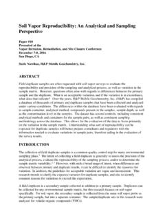
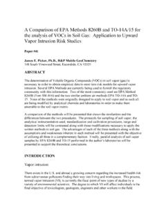
7 Field Records The field technician maintains a log sheet summarizing: Sample identification Probe location Date and time of sample collection Sampling depth Identity of samplers Weather conditions Sampling methods and devices soil gas purge volumes Volume of soil gas extracted Vacuum of canisters before and after samples collected. Apparent moisture content (dry, moist or saturated etc.) of the sampling zone Chain of custody protocols and records used to track samples from sampling point to analysis. H&P Mobile Geochemistry 10/04 4 Photo 1 soil gas sampling materials: sample collection train, Vapor implants, mini-can (400 cc), purging syringe. Photo 2 Sub-Slab Vapor implant (1/8 OD) and cap. Nylon tubing can be cut to any length. H&P Mobile Geochemistry 10/04 5 Photo 3 Drilling hole through slab (1/2 OD).
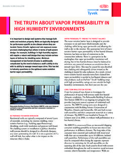
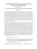
8 Photo 4 Surface completions. Left: tubing coiled in hole. Removable plug installed to make flush with surface. Right: cemented flush to surface (hole slightly recessed purposely to enable fitting to be visible in photo). H&P Mobile Geochemistry 10/04 6 Photo 5 Collecting sample with 60 cc syringe. Note small dead-volume of tubing connecting syringe to implant.. Photo 6 Purging implant & sampling train with 60 cc syringe. Note small dead-volume of tubing connecting syringe to implant. H&P Mobile Geochemistry 10/04 7 Photo 7 Collecting soil gas sample in mini-can (400 cc). Photo 8 Collecting sample in larger canister (6 liter). No sampling train is required since the canister is already equipped with valve, vacuum gauge, and flow choke.