Transcription of Subject: Emergency Diesel Generator
1 OPERATIONS MANUAL SYSTEM OPERATING PROCEDURE Facility Name, Building, Worksite or Plant ID: Subject: Emergency Diesel Generator Approved by: Document Version Number: Issue Date: Generator Location: Prepared By: LEGAL DISCLAIMER: This Operations Manual for an Emergency Standby Generator is provided by Diesel Service & Supply to be a general guide, template and reference point for creating your own unique Operations Manual for your specific facility, plant, building or worksite. Since power generators are complex electrical pieces of equipment, certain aspects of the document will not apply to all situations. Any time electrical work and details are involved we always suggest consulting a certified electrician and/or experienced Generator technician for final approval or doing any on-site services that may be required. Since this is intended as a guide only, Diesel Service & Supply assumes no responsibility for the content and references contained within this document.
2 TABLE OF CONTENTS SECTION TITLE PAGE System 3 A. Description .. 3 B. Control and 4 C. Design Conditions .. 5 Operating Precautions and Limitations .. 5 Operating Prerequisites .. 8 Normal A. Normal Startup Normal Operation ..10 A. Normal Operation ..10 Normal Shutdown ..11 Abnormal/ Emergency A. Emergency Operation ..11 B. Abnormal Operating Conditions ..12 C. Emergency Shutdown ..12 TABLES Table 1, Major System Instruments and Table 2, Annunciator Emergency Diesel Generator REFERENCE DIAGRAMS Emergency Generator Typical Fuel Emergency Generator Typical Load CHECKLISTS Pre-Startup Normal Valve Lineup - for fuel and cooling water if water cooled Emergency Diesel Generator Connection Diagram Sheets Motor Control Center and One Line Diagram Alarm System Schematics for the Emergency Generator if Applicable Emergency Generator Synchronizing and Metering Emergency Generator Controls REFERENCES & APPENDICES Basic Diagram of your Fuel and Load Center Layouts Instruction Manual for your particular Generator set should be included Manufacturer Specification/Data Sheet for your genset should also be attached OPERATING PROCEDURE Emergency Diesel Generator INTRODUCTION This Operating Procedure shall be used by operating personnel at the facility referenced above to operate the Emergency Diesel Generator and the associated auxiliary equipment.
3 Only the most recently approved revision of this document shall be used and previous versions shall be destroyed to prevent confusion. The following personnel shall have the specified roles and responsibilities: _____ _____ _____ SYSTEM DESCRIPTION A. DESCRIPTION The Emergency Diesel Generator is provided to maintain power to those loads which are necessary for protection of equipment and personnel during a total loss of station and off-site power. The Emergency Diesel Generator is located at and is connected to Motor Control Center by cable through a locally mounted motor operated circuit breaker and manually operated disconnect switch. The Emergency Diesel Generator manufactured by consists of one turbo charged Diesel engine coupled to the Generator shaft and mounted on a common structural steel base with spring vibration isolators. The engine is complete with its own battery starting system, lube oil pump, filter and coolers, jacket water cooling pump, radiator, fan with guard and shroud, air intake filter, and exhaust silencer.
4 The Generator is also provided with its own voltage regulator, protective devices, and shaft mounted exciter. A gallon fuel oil d ay tank with a working capacity of about consumption is mounted separately from the engine. A gear driven pump for pumping fuel from the day tank to the engine is furnished. Fuel transfer from Diesel oil s torage tank to day tank is by an electric motor driven rotary type pump which is controlled by a level switch on the day tank. The day tank pump is rated for 120 VAC and receives power from lighting panel# . A control cabinet, located on the Generator , is supplied for mounting of engine controls, electric meters, relays, and voltage regulator. ADDITOIONAL DETAILS FOR YOUR SYSTEM: OPERATING PROCEDURE Emergency Diesel Generator B. CONTROL AND PROTECTION The Emergency Diesel Generator can be controlled locally or from . Generator voltage control, governor control and synchronization control as well as operation of the Generator circuit breaker and MCC feeder breaker can be accessed from the locations above.
5 A mode selector switch, located locally, with "MANUAL-OFF-AUTO" positions is typically provided to allow for routine testing of the Emergency Generator . In the "MANUAL" position, the mode selector switch allows starting only from the local control panel. All automatic control and manual control from the remote panel is disabled. In the "AUTO" position, the switch allows for full automatic starting, running, and shutdown of the Emergency Generator . Manual control from the remote panel is allowed only with the mode selector switch in the "AUTO" position. A "MANUAL-AUTO" switch is also typically provided on the remote panel to allow remote control of the Emergency Generator . In the "MANUAL" position, the switch causes the Diesel engine to start. In the "AUTO" position, manual control is allowed from the local control panel as well as full automatic starting, running, and shutdown of the Emergency Generator . Both the mode selector switch and the remote mounted "MANUAL-AUTO" switch must be in the "AUTO" position for full automatic control of the Emergency Generator .
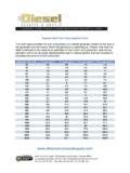
6 With both switches in the "AUTO" position, the Emergency Generator will start automatically upon loss of voltage on your facility load center. The local controls automatically regulate speed, voltage, and frequency. As soon as the Generator reaches about 1500 RPM, a relay trips the feeder breaker in your facility load center which feeds your facility load center and closes the Emergency Generator main breaker. If t he load center feeder breaker is racked out, the Emergency Generator main breaker will not close due to electrical interlocks. Upon return of normal power supply, the Emergency Generator main breaker trips and the load center feeder breaker closes automatically. ADDITONAL PROTECTION DETAILS FOR YOUR ENVIRONMENT: OPERATING PROCEDURE Emergency Diesel Generator C. DESIGN CONDITIONS (Fill in the blanks with your particular Generator set s data) Mechanical Data Engine Type: Engine Manufacturer: Model Number: RPM: Brake Horsepower: Fuel Consumption: Fuel Type: Lubricating Oil Type: Cooling Medium: Auto Start/Stop: Safety Shutdown: Engine Mounted Radiator: Electrical Data Manufacturer: Generator Capacity: KW, KVA Generator Rating: Model Number: Serial Number: Model Year: Hours: Voltage: Phase: Hertz: Amps: Circuit Breaker: Number of Leads: Muffler: Enclosure: Generator Control Panel: Synchronous Speed: Cooling Medium: Exciter: Full load voltage: Full load amps: Starting System/Battery: Volt, lead-acid battery, with battery charger Insulation class: Fuel Tank Type and Storage: Note Additional Electrical Specs Here.
7 OPERATING PRECAUTIONS AND LIMITATIONS The following summary of operating precautions and limitations is generally applicable to all system operations. Operating personnel must be familiar with all of these limitations. A. Adhere to plant safety rules and observe manufacturer safety precautions. B. If any maintenance work has been done, VERIFY the work has been completed, the work clearances have been removed, the areas where work took place are cleared and do not present any risk during system operation, and the equipment, circuits, sensors, etc. are ready for operation. C. Prior to startup, a visual inspection of all system components should be performed to ensure personnel safety and that all components are ready for operation. Corrective action shall be taken to correct any deficiencies. D. Before handling any Hazardous Chemicals associated with the performance of this procedure, all operators shall be familiar with the precautions and first-aid instructions provided in the applicable Material Safety Data Sheet (MSDS).
8 A copy of each plant MSDS should always be available in the location of your facilities MSDS documentation. E. personnel shall regularly monitor the Emergency Diesel Generator remote, if available, and local indicators for the conditions and parameters listed in Table 1 below in order to recognize and respond to the approach or a ctuation of any listed alarm or automatic "trip" function. All operating personnel should be familiar with the expected normal operating parameters and with the listed alarm or trip setting (if one is listed) for each listed control function. F. The Emergency Generator is a standby unit and should be kept well maintained at all times and periodically test run once a week. G. Check all local gauges when Emergency Generator is running. H. Check that Diesel oil transfer pump on day tank is in good working condition. I. All controls must remain in the "AUTO" mode or position. J. Check to see that all batteries are fully charged and in good working condition.
9 K. Check that Diesel oil storage and day tanks are kept full at all times and the fuel has been properly maintained. L. Document Any Additional Details for your Facility below (including details on specific motors and soft starts, automatic transfer switches, transformers, etc.): OPERATING PROCEDURE Emergency Diesel Generator Table 1, Major System Instruments and Settings Instrument Control/Indicator Function Settings: Located Locally: (on Diesel storage tank) Low Oil Pressure Switch psi (alarm and trip) High Circulating Water Temperature F (alarm and trip) Over-s peed Control rpm (alarm and trip) Crank cut-out: rpm (trip) Speed Switch rpm Oil temperature F- F (Normal) Time Delay Engine "Auto Start": - seconds Time Delay Engine "Cool-down" minutes Level indicator - monitors level of Diesel oil inside of storage tank Range: 0 to gallons Table 1, Major System Instruments and Settings Instrument Control/Indicator Function Settings: Located Locally.
10 (on Diesel Generator or control panel) Ammeter - Monitors Generator output Amps (Normal) Frequency Meter Indicates Generator output frequency Hz (Normal) Kilowatt Meter - Monitors Generator output power Watts (Normal) Incoming Voltmeter - Indicates bus voltage at source (If any) volts. Synchroscope - Indicates when Generator is synchronized with system. Running Volts - Indicates Generator output voltage Volts (Normal). Additional Settings & Notes (include any primary details below): Table 2, Annunciator Alarms Window No. Description Condition Alarmed (Only used if your Generator is equipped with a local annunciator and/or your facility is equipped with a remote annunciator) Emergency Generator oil pressure cooling water temperature tank fuel level tank fuel level failureOPERATING PROCEDURE Emergency Diesel Generator OPERATING PREREQUISITES A. Ensure all system flow path and instrument valves are properly aligned. B. Ensure that your facility s low voltage electrical system is working properly, if testing, or was working properly prior to loss of voltage.