Transcription of SUBJECT: TROUBLE SHOOTING GUIDE FOR R.O. BOOST …
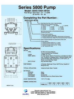
1 Aquatec Water Systems IMI-147, Revision B, 4/04 Page 1 of 3 subject : TROUBLE SHOOTING GUIDE FOR BOOST PUMP SYSTEMS DESCRIPTION The BOOST pump system normally includes at least 3 components (see diagram #1): 1. A 6800 or 8800 series pump, fitted with an integral by-pass mechanism, and driven by a low voltage permanent magnet motor. 2. A step down transformer designed to power the motor and one or more accessories. 3. A switch that cuts the electricity from the transformer to the pump when the air charged storage tank pressure reaches a pre-established switch shut off setting, then re-starts the pump as purified water is withdrawn from the tank.
2 Other performance enhancing accessories that can be powered by our .8 amp, or amp transformers, are a feed water shut off valve (ESO), and an automatic membrane fast flush valve (AFT), that can also double as a flow restrictor (AFR). DIAGRAM 1 Aquatec Water Systems IMI-147, Revision B, 4/04 Page 2 of 3 ANALYZING FIELD PROBLEMS A. The pump will not run: at the source to determine where the electrical current flow has been interrupted. Use a multi-meter to check the line voltage, and the transformer output. If the transformer is not functioning properly its current capacity may have been exceeded.
3 Please consult the factory. the transformer is properly sized, and is delivering the correct voltage to the system, remove the holding tank pressure switch (PSW) from the system by disengaging both connectors, and connecting the pump directly to the transformer. a. If the pump now runs, the pressure switch is faulty, and needs adjusted or replaced. b. If the pump still fails to run, the electrical path has been interrupted within the motor, and should be returned to the factory for repair. B. The flow and/or pressure is too low: Most Aquatec BOOST pumps are designed to limit the maximum output pressure to 110 psi, to protect the membrane and other components from damage.
4 The normal operating pressure as measured after the pump, and before the membrane, will be approximately 80 psi. The flow rate of the 6800 series pump during operation is about 500 ml/min. The 8800 is double that flow. If these parameters are not being met, please check the following: the pump properly sized to handle the production rate of the membrane, plus the brine flow allowed by the restrictor (usually 4 or 5 times the permeate production)? 2. Is the system receiving adequate feed water? The pump s inlet chamber must be flooded to prevent performance robbing air ingestion into the compression chambers.
5 3. Debris entering the pump, such as residue from an activated carbon filter improperly located on the inlet side of the pump, may restrict the pumping operation. Consult the factory for valve cleaning instructions. C. The pump will not shut off: This is usually caused by a pressure switch that is: 1. Not mounted to properly sense the pressure in the storage tank, or 2. Will not open at a pressure less than the minimum allowed by a hydraulic shut off valve. Check with the supplier of the RO system. If the shut off valve stops the flow of feed water before the storage tank reaches the shut off pressure setting of the switch, the switch will remain closed, and the pump will run continuously.
6 This conflict can be eliminated by removing the hydraulic shut off valve, and adding Aquatec s Electronic Shut Off (ESO). The ESO is triggered by the same pressure switch that controls the BOOST pump. If the hydraulic shut of valve cannot be removed, the pressure switch can be adjusted to open at a lower pressure, or may be replaced by a 40 psi PSW. 3. Check carbon prefilter. Replace if necessary. A partially or fully clogged carbon filter may cause the pump to run continuously. D. The pump operation is too noisy: BOOST pumps operate at relatively slow speeds, accounting for their quiet operation.
7 Pumps that exceed expected noise levels usually have one of the following problems: 1. Entrapped air (which will eventually dissipate). Make sure air is not being drawn into the pump. 2. Water may have damaged the bearings, or other motor components. Check for internal leaks, as well as water entering the motor from an external source. 3. Squeaking may be associated with the by-pass mechanism; brush contact with the commutator surface; or inadequate lubrication in the rear bearing. Consult the factory. Aquatec Water Systems IMI-147, Revision B, 4/04 Page 3 of 3 E.
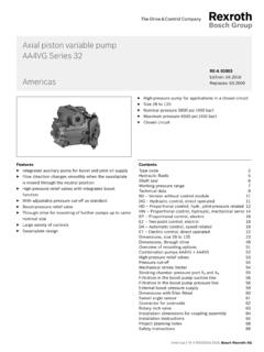
8 The pump is causing electrical noise interference: 1. Try locating the pump on a dedicated electrical circuit, separate from the device that is being interfered with. 2. Consult factory for pumps available with electronic noise suppression. F. Can a Permeate Pump and a Booster Pump be used together in an system? Yes. The Booster Pump increases the feed water pressure to the membrane, while the Permeate Pump is located after the membrane and eliminates the performance robbing back pressure created by a full, or filling, air charged storage tank (see diagram # 2).
9 DIAGRAM 2