Transcription of Suggested Electric Fan Wiring Diagrams - DaveBarton.com
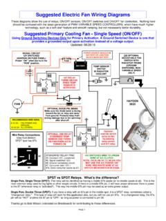
1 SPST vs SPDT Relays. What s the difference? Single Pole, Single Throw (SPST): This relay will be identified as having a middle 87b spade (or no middle spade at all). This is the most common relay used for fog lights or other simple circuits. If there is a middle 87b pin, it will have power whenever there is power to the 87 (whenever relay is activated ). This way the middle 87b pin may be used as an extra power output. Single Pole, Double Throw (SPDT): If you have a relay with an 87a pin in the middle spot, it is a SPDT relay, sometimes called a "changeover relay." This type of relay will work for this application also, but you will not use pin 87a. In a changeover relay, the 87a pin will be HOT anytime the 87 pin is "OFF," so long as power is connected to pin 30. Thanks go to Bob Wilson (volvodad on Brickboard) for contributing to these differences. Suggested Electric Fan Wiring Diagrams PAGE 1 These Diagrams show the use of relays, ON/OFF sensors, ON/OFF switches and ON/OFF fan controllers.
2 Nothing here should be confused with the latest generation of PWM VARIABLE SPEED CONTROLLERS, which have much higher technology, such as a soft start feature and smooth ramping, but not necessarily better durability. Suggested Primary Cooling Fan - Single Speed (ON/OFF) Using Ground Switching Devices Only for Primary Activation. A Ground Switched Device is one that provides a grounded output upon activation instead of a voltage output. Updated: 08/28/16 87 87b 86 85 30 Mini Relay Connections View from Bottom SPST type has 87b STANDARD RELAY PINS 30: Constant 12V, unswitched 85: Signal (switched 12V) 86: Ground (completes circuit) 87: Consumer (fan) 12V + 87b: Extra consumer (same as 87) RECOMMENDED WIRE SIZES: 8-10 GA: FAN POWER AND GROUND. 16-18 GA: ALL OTHERS. SIGNAL CIRCUIT 12V SWITCHED (IGNITION OR FUSE PANEL) Power ON when key is in the RUN position. 1ST RELAY TURNS ON FAN WHEN TEMP SENSOR IS ACTIVATED BATTERY 86 87 30 85 12V SWITCHED WIRE TO GREEN WIRE AT A/C CLUTCH.
3 NOTE: OR IN AN 84 TO 89 240 YOU MAY USE THE A/C POWER ON WIRE: RED/WHITE WIRE AT AC SWITCH MICROSWITCH IN DASH. 30 AMP FUSE 86 87 30 85 OPTIONAL 2ND RELAY OVERRIDES TEMP SENSOR AND TURNS ON FAN WHEN A/C IS TURNED ON TEMP SENSOR SWITCH IN RADIATOR COOLANT OR OPTIONAL ADJUSTABLE FAN SWITCH WITH RADIATOR PROBE (GROUND SWITCHING, NON-VARIABLE SPEED ONLY) 5 AMP FUSE POWER SOURCE SHOULD BE BATTERY OR JUNCTION BLOCK NEAR BATTERY FAN Optional override switch turns on fan, by-passing temp sensor and A/C relay. HAYDEN 3653 OPTIONAL DIODE PN: IN5408 Make sure the diode band is facing toward the fan or relay and away from ground. Protects relay from arcing damage due to fan spinning after shut-off. SPST vs SPDT Relays. What s the difference? Single Pole, Single Throw (SPST): This relay will be identified as having a middle 87b spade (or no middle spade at all). This is the most common relay used for fog lights or other simple circuits. If there is a middle 87b pin, it will have power whenever there is power to the 87 (whenever relay is activated ).
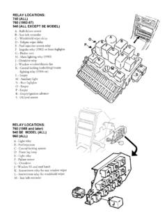
4 This way the middle 87b pin may be used as an extra power output. Single Pole, Double Throw (SPDT): If you have a relay with an 87a pin in the middle spot, it is a SPDT relay, sometimes called a "changeover relay." This type of relay will work for this application also, but you will not use pin 87a. In a changeover relay, the 87a pin will be HOT anytime the 87 pin is "OFF," so long as power is connected to pin 30. Thanks go to Bob Wilson (volvodad on Brickboard) for contributing to these differences. Suggested Electric Fan Wiring Diagrams Suggested Primary Cooling Fan - Single Speed (ON/OFF) Using 12 Volt Switching Devices Only for Primary Activation NOTE: Most stand-alone adjustable thermostats ( : Hayden, Flex-a-Lite or Perma-Cool brands) can provide a 12 volt output when activated. Relays shown in these Diagrams can provide options for useful features such as an AC override ON and/or manual override ON. PAGE 2 STANDARD RELAY PINS 30: Constant 12V, unswitched 85: Signal (switched 12V) 86: Ground (completes circuit) 87: Consumer (fan) 12V + 87b: Extra consumer (same as 87) RECOMMENDED WIRE SIZES: 8-10 GA: FAN POWER AND GROUND.
5 16-18 GA: ALL OTHERS. 12V SWITCHED WIRE TO GREEN WIRE AT A/C CLUTCH. NOTE: OR IN AN 84 TO 89 240 YOU MAY USE THE A/C POWER ON WIRE: RED/WHITE WIRE AT AC SWITCH MICROSWITCH IN DASH. OPTIONAL 2ND RELAY OVERRIDES TEMP SWITCH AND TURNS ON FAN WHEN A/C IS TURNED ON FAN ADJUSTABLE FAN SWITCH/THERMOSTAT WITH RADIATOR PROBE (12V SWITCHING, NON-VARIABLE SPEED ONLY) BATTERY 30 AMP FUSE POWER SOURCE SHOULD BE BATTERY OR JUNCTION BLOCK NEAR BATTERY 86 87 30 85 1ST RELAY TURNS ON FAN WHEN TEMP SWITCH IS ACTIVATED 5 AMP FUSE SIGNAL CIRCUIT 12V SWITCHED (IGNITION OR FUSE PANEL) Power ON when key is in the RUN position. + + 86 87 30 85 Optional override switch turns on fan, by-passing temp sensor and A/C relay. These Diagrams show the use of relays, ON/OFF sensors, ON/OFF switches and ON/OFF fan controllers. Nothing here should be confused with the latest generation of PWM VARIABLE SPEED CONTROLLERS, which have much higher technology, such as a soft start feature and smooth ramping, but not necessarily better durability.
6 HAYDEN 3653 OPTIONAL DIODE PN: IN5408 Make sure the diode band is facing toward the fan or relay and away from ground. Protects relay from arcing damage due to fan spinning after shut-off. 87 87b 86 85 30 Mini Relay Connections View from Bottom SPST type has 87b SPST vs SPDT Relays. What s the difference? Single Pole, Single Throw (SPST): This relay will be identified as having a middle 87b spade (or no middle spade at all). This is the most common relay used for fog lights or other simple circuits. If there is a middle 87b pin, it will have power whenever there is power to the 87 (whenever relay is activated ). This way the middle 87b pin may be used as an extra power output. Single Pole, Double Throw (SPDT): If you have a relay with an 87a pin in the middle spot, it is a SPDT relay, sometimes called a "changeover relay." This type of relay will work for this application also, but you will not use pin 87a. In a changeover relay, the 87a pin will be HOT anytime the 87 pin is "OFF," so long as power is connected to pin 30.
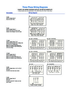
7 Thanks go to Bob Wilson (volvodad on Brickboard) for contributing to these differences. RECOMMENDED WIRE SIZES: 8-10 GA: FAN POWER AND GROUND. 16-18 GA: ALL OTHERS. Suggested Electric Fan Wiring Diagrams Converting a 12 Volt Switch into a Ground Switch These Diagrams show the use of relays, ON/OFF sensors, ON/OFF switches and ON/OFF fan controllers. Nothing here should be confused with the latest generation of PWM VARIABLE SPEED CONTROLLERS, which have much higher technology, such as a soft start feature and smooth ramping, but not necessarily better durability. If you have an adjustable thermostat that uses 12 VOLT SWITCHING ONLY, such as the popular Hayden or Flex-a-Lite brand thermostats with built-in relays, you may normally only use it with a diagram use it with any diagram showing a need for a 12 VOLT SWITCHED DEVICE. if you follow these steps you may convert it to a GROUND SWITCHED DEVICE using a simple SPST relay.
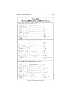
8 ADJUSTABLE FAN SWITCH/THERMOSTAT WITH BUILT-IN RELAY AND RADIATOR PROBE (12V SWITCHING, NON-VARIABLE SPEED ONLY) 86 87 30 85 5 AMP FUSE SIGNAL CIRCUIT 12V SWITCHED (IGNITION OR FUSE PANEL) Power ON when key is in the RUN position. + + THIS WILL BE YOUR NEW GROUND SWITCHED OUTPUT. IT MAY BE USED AS A GROUND SWITCHED DEVICE FOR ANY DIAGRAM NEEDING ONE. PAGE 3 HAYDEN 3647 87 87b 86 85 30 Mini Relay Connections View from Bottom SPST type has 87b STANDARD RELAY PINS 30: Constant 12V, unswitched 85: Signal (switched 12V) 86: Ground (completes circuit) 87: Consumer (fan) 12V + 87b: Extra consumer (same as 87) PRIMARY COOLING FAN DUAL FANS (with Dual Relays) - SINGLE SPEED (ON/OFF) Using Ground Switched Devices Only for Primary Activation Using dual relays for two fans is not required. You could use one relay. However two relays will divide the load. And if a relay fails, you will still have one fan running. RECOMMENDED WIRE SIZES: 8-10 GA: FAN POWER AND GROUND.
9 16-18 GA: ALL OTHERS. PAGE 4 OPTIONAL RELAY OVERRIDES TEMP SENSOR AND TURNS ON FANS WHEN A/C IS TURNED ON BATTERY 86 87 30 85 86 87 30 85 Optional override switch turns on fan, by-passing temp sensor and A/C relay. 30-40 AMP FUSE 86 87 30 85 TEMP SENSOR SWITCH IN HOTTEST PART OF RADIATOR MAIN RELAYS TURN ON FANS WHEN TEMP SENSOR IS ACTIVATED 12V SWITCHED WIRE. MAY BE GREEN WIRE AT A/C CLUTCH. NOTE: OR IN AN 84 TO 89 240 YOU MAY USE THE A/C POWER ON WIRE: RED/WHITE WIRE AT AC SWITCH MICROSWITCH IN DASH. SIGNAL 12V SWITCHED (FUSE PANEL) Power ON when key is in the RUN position POWER SOURCE SHOULD BE BATTERY OR JUNCTION BLOCK NEAR BATTERY 5 AMP FUSE OR OPTIONAL ADJUSTABLE FAN SWITCH WITH RADIATOR PROBE (GROUND SWITCHING, NON-VARIABLE SPEED ONLY) 30-40 AMP FUSE FAN 1 FAN 2 HAYDEN 3653 OPTIONAL DIODES PN: IN5408 Make sure the diode band is facing toward the fan or relay and away from ground. Protects relay from arcing damage due to fan spinning after shut-off.
10 STANDARD RELAY PINS 30: Constant 12V, unswitched 85: Signal (switched 12V) 86: Ground (completes circuit) 87: Consumer (fan) 12V + 87b: Extra consumer (same as 87) 87 87b 86 85 30 Mini Relay Connections View from Bottom SPST type has 87b PRIMARY COOLING FAN DUAL FANS (with Dual Relays) - SINGLE SPEED (ON/OFF) Using 12 Volt Switched Devices Only for Primary Activation Using dual relays for two fans is not required. You could use one relay. However two relays will divide the load and if a relay fails, you will still have one fan running. PAGE 5 12V SWITCHED WIRE TO GREEN WIRE AT A/C CLUTCH. NOTE: OR IN AN 84 TO 89 240 YOU MAY USE THE A/C POWER ON WIRE: RED/WHITE WIRE AT AC SWITCH MICROSWITCH IN DASH. 86 87 30 85 OPTIONAL AC RELAY OVERRIDES TEMP SWITCH AND TURNS ON FANS WHEN A/C IS TURNED ON ADJUSTABLE FAN SWITCH/THERMOSTAT WITH RADIATOR PROBE (12V SWITCHING, NON-VARIABLE SPEED ONLY) BATTERY POWER SOURCE SHOULD BE BATTERY OR JUNCTION BLOCK NEAR BATTERY 86 87 30 85 MAIN RELAYS TURN ON FANS WHEN TEMP SWITCH IS ACTIVATED 5 AMP FUSE Optional override switch turns on fans, by-passing temp sensor and A/C relay.