Transcription of Suggested Modifications to ASTM Test Method E 477
1 SOUND & VIBRATION/JUNE 2011 ASTM E-477 is the current standard test Method used in North America for evaluating the acoustic and aerodynamic perfor-mance of duct silencers. The test Method uses, at a minimum, a source chamber, a test duct (that includes a test specimen), and a reverberation chamber. If testing under flow is desired, the system also requires a fan chamber that can provide quiet airflow through the test duct. The results of the test Method yield silencer insertion loss, self-generated noise, both as a function of acoustic frequency and flow velocity, and pressure drop. There are several problems with the current test Method , some that are being addressed by the ASTM working group that is responsible for the development and maintenance of this standard. This article highlights the most significant problems associated with the current standard and proposes Modifications to the standard that should, if adopted, improve the intralaboratory reproducibility of the test decades the commercial duct silencer industry throughout North America has relied on ASTM E 4771 as a test standard for measuring the dynamic insertion loss, self-generated noise, and pressure drop of passive duct silencers.
2 Historically, there has been great concern in the acoustical consulting community regarding the accuracy and reliability of manufacturers acoustical performance data for duct silencers. Round-robin test results have shown rela-tively poor agreement between several NVLAP-certified (National Voluntary Laboratory Accreditation Program) testing labs over a wide frequency range. There are several possible reasons why different labs can get significantly different answers when testing the same silencer. Some of these reasons are possibly due to the unique physical characteristics of the individual labs, but there are problems with the standard itself that also contribute to this situation. This article identifies specific deficiencies in the current standard and presents recommendations for Modifications that should improve the agreement in future round-robin the ASTM E 477 test procedure has three compo-nents:Determine the insertion loss of the test specimen, which could be a duct silencer or a section of acoustically lined ductwork, as a function of air flow and acoustic the pressure drop of the test specimen as a function of air the self-generated flow noise of the test specimen as a function of acoustic frequency and air acoustic measurements are conducted in one-third-octave bands.
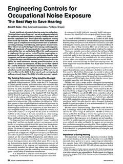
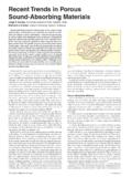
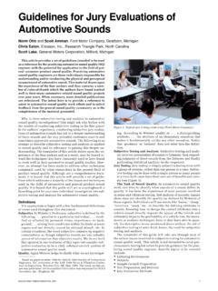
3 These three characteristics (insertion loss, pressure drop, and self-noise) define the overall performance of the duct silencer. There is a fourth component that is not evaluated in the current version of the standard, and that is the sound power radiated by the casing of the silencer. While casing -radiated noise from a duct silencer is not an important issue in most applications, there are some situations where this can be important. This matter will be discussed in greater detail later in this 1 presents a generic drawing of a typical E 477 lab that is equipped to measure acoustical performance with air flow. (There is at least one lab in the that is designed to measure insertion loss of duct silencers and acoustically lined ductwork in accordance with ASTM E 477 without air flow, but such a facility cannot measure pressure drop or self-generated noise, which are critical performance factors of duct silencers.)
4 The main components of the E 477 lab are the:Signal source chamber Test duct The reverberation chamber Fan chamber with connecting ductwork The source chamber contains one or more loudspeakers that generate a high level of pink noise (equal energy/percent frequency, 1/f). Typical sound levels inside the source chamber range from 110 to 130 dBA during testing. Noise from the loudspeaker propagates down the test duct through the test specimen into the reverbera-tion chamber. According to the standard, the test duct must be constructed of minimum 14-gauge (2-mm -thick) steel to minimize breakout, but some labs use steel ductwork as heavy as ( ) thick. The overall length of the test duct is usually somewhere between 15 m (50 ft) and 30 m (100 ft).When testing elbow silencers, the test duct may also contain a 90-degree elbow. The reverberation chamber is used to measure the total sound power radiated by the test duct opening using the methodology specified in ANSI (ISO 3741).
5 For measure-ments with air flow, a separate fan chamber is required with con-necting ductwork. The fan chamber and connecting ductwork must be designed to reduce the fan-generated noise to an insignificant level throughout the frequency range of interest. This typically requires vibration isolators on the fan, silencers at the fan inlet and outlet, and silencers in connecting addition, for measurements with positive (sound propagating in the same direction as the air) and negative (sound propagating in the opposite direction) air flow, the fan chamber must be designed to create air flow in both directions. This can be accomplished using a reversible fan, a fan that can easily be rotated inside the fan chamber, or using internal dampers or doors to change air flow direction without modifying the fan s rotation or orientation. Op-erating the fan with a variable-frequency drive is very helpful for achieving the desired flow rate for each test Test ResultsThere have been at least three round robins conducted in the last 10 years to ascertain the precision of the ASTM E 477 test Method for determining the acoustical performance of duct silenc-ers.
6 The test silencers ranged in length from m (3 ft) to 3 m (10 ft). The number of test labs for each round robin varied from a low of four to a high of six. The sample size is limited because of the number of test facilities available. In North America there are only seven known labs known that have facilities to test duct silencers with air 2 and 3 present the measured repeatability and repro-ducibility standard deviations for one of the round robin tests . From these results we can easily see that all of the labs tend to get approximately the same answer when they repeat the test several times (as shown by the repeatability curves marked by solid black Suggested Modifications toASTM Test Method E 477 Jerry G. Lilly, JGL Acoustics, Inc., Issaquah, WashingtonBased on a paper presented at Noise-Con 10, Institute of Noise Control Engineering, Baltimore, MD, 1.)
7 Typical E 477 lab layout. FanchamberSourcechamberReverberationroom Elbow test ductTest SOUND & VIBRATION/JUNE 2011 13squares). When different labs test the same specimen, however, there is a wide range of variation in the results (as shown by the reproducibility curves marked by solid red circles). In terms of insertion loss, the reproducibility is poorest at 50 Hz, but repro-ducibility is also unacceptable in the 250 to 2500 Hz and 5000 to 10,000 Hz frequency regions as well. The reproducibility of flow-generated noise is also extremely poor at low frequencies and again at high frequencies (see Figure 3). In the mid-frequency region, the flow-generated noise reproducibility is much better but certainly not as good as it should be. We do not attempt to address issues that impact the accuracy of flow-generated DeficienciesThere are several deficiencies in the current standard, and this article focuses on three areas that may have the greatest impact on the poor precision exhibited by the round-robin test results:Source chamber characteristics Flanking sound transmission Empty duct resonances The first two areas are currently being addressed by the ASTM working group in charge of maintaining the standard, and I hope that a new standard will soon be approved that will correct these deficiencies.
8 The third area is being neglected by the working group for the time being but will likely be addressed soon after the next version of the standard is Chamber Characteristics. In the current version of the standard (ASTM E 477-06a), there are very few requirements for the source chamber. There is no minimum size Suggested (other than being large enough to install the ductwork and loudspeaker), and there are no acoustical performance standards (other than a requirement that the interior surfaces of the chamber contain a minimal amount of sound-absorbing material. The source chamber is a critical component of the test Method , and it is worthy of an acoustical performance specification. The most important feature of the source chamber is to generate a constant, high-level, acoustic signal that will create a constant, in-duct sound power level at the inlet of the test specimen with or without the test specimen in the test duct.)
9 If the presence of the test specimen in the test duct changes the impedance seen by the loudspeaker, then the sound power radiated by the loudspeaker may be different when the test specimen is removed or inserted into the test duct. Such a condition could certainly change the measured insertion loss of the test following Modifications are recommended to Section of the standard to improve the characteristics of the source chamber:Require a measurement microphone (with a windscreen if air flow is present) to be placed at a fixed location inside the source chamber near the radiating surface of the loudspeaker. The sig-nal from this microphone should be monitored and analyzed simultaneously by the same data acquisition system that is used to collect the data from the microphone(s) in the reverberation chamber. If when comparing the empty duct test to the test with the test specimen, the sound pressure level in the source chamber deviates by more than 1 dB in any frequency band, the test is invalid and should be repeated until the variation is less than 1 a minimum size of 10 cubic meters for the source chamber.
10 This will provide adequate space for placing the loudspeaker(s) and the monitor microphone without obstruct-ing Sound Transmission. Flanking sound is any sound that travels from the source chamber to the reverberation cham-ber that does not pass through the test specimen. Like ambient noise, flanking sound will limit the laboratory s ability to measure insertion loss. However, unlike ambient noise (which can easily be measured), flanking sound typically goes totally unnoticed, because it is present only when the source chamber is operating. The round-robin tests noted earlier were all conducted using the 1999 version of the standard, which had no requirement to measure the flanking sound transmission, let alone correct data for flanking effects. The 1999 version of the standard made suggestions as to how to assess the magnitude of the flanking sound, but there were no specific recommendations as to how to perform the flanking test and certainly no requirement that it be done.