Transcription of Sunderarajan S. Mohan, Maria del Mar Hershenson, …
1 IEEE JOURNAL OF SOLID-STATE CIRCUITS, VOL. 34, NO. 10, OCTOBER 19991419 Simple Accurate Expressions for Planar spiral InductancesSunderarajan S. mohan , Maria del Mar hershenson , stephen P. Boyd, and Thomas H. LeeAbstract We present several new simple and accurate expres-sions for the DC inductance of square, hexagonal, octagonal,and circular spiral inductors. We evaluate the accuracy of ourexpressions, as well as several previously published inductanceexpressions, in two ways: by comparison with three-dimensionalfield solver predictions and by comparison with our own measure-ments, and also previously published measurements.
2 Our simpleexpression matches the field solver inductance values typicallywithin around 3%, about an order of magnitude better thanthe previously published expressions, which have typical errorsaround 20% (or more). Comparison with measured values givessimilar results: our expressions (and, indeed, the field solverresults) match within around 5%, compared to errors of around20% for the previously published expressions. (We believe mostof the additional errors in the comparison to published measuredvalues is due to the variety of experimental conditions underwhich the inductance was measured.)
3 Our simple expressions are accurate enough for design andoptimization of inductors or of circuits incorporating , since inductor tolerance is typically on the order of sev-eral percent, more accurate expressions are not really neededin Terms CMOS analog integrated circuits, inductors,integrated circuit design, integrated circuit INTRODUCTIONTHE RISING demand for low-cost radio frequency in-tegrated circuits (RF-IC s) has generated tremendousinterest in on-chip passive components [1]. Currently, thereare several integrated resistor and capacitor options and mostof these implementations are easy to model.
4 Considerableeffort has also gone into the design and modeling of inductorimplementations, of which the only practical options are bondwires and planar spiral geometries. Although bond wirespermit a high quality factor () to be achieved, with typical s in the 20 50 range, their inductance values are constrainedand can be rather sensitive to production fluctuations. On theother hand, planar spiral inductors have limited s, but haveinductances that are well-defined over a broad range of processvariations. Thus, planar spiral inductors have become essentialelements of communication circuit blocks such as voltagecontrolled oscillators (VCO s), low-noise amplifiers (LNA s),mixers, and intermediate frequency filters (IFF s).
5 Square spirals are popular because of the ease of theirlayout. Squares are generated easily even in simple Manhattan-style layout tools (such as MAGIC). However, other polygonalspirals have also been used in circuit design. Some designersprefer polygons with more than four sides to improve per-Manuscript received November 5, 1998; revised July 12, 1999. This workwas supported by authors are with the Electrical Engineering Department, StanfordUniversity, Stanford, CA 94305 USA (e-mail: Item Identifier S 0018-9200(99) Among these, hexagonal and octagonal inductorsare used widely.)
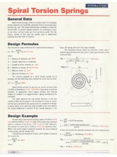
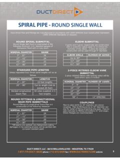
6 Fig. 1(a) (d) shows the layout for square,hexagonal, octagonal, and circular inductors, respectively. Fora given shape, an inductor is completely specified by thenumber of turns, the turn width, the turn spacing, andany one of the following: the outer diameter, the innerdiameter, the average diameter,or thefill ratio,defined thickness of the inductor has only a very small effect oninductance and will therefore be ignored in this facilitate the design of such components, significant workhas gone into modeling spiral inductors using lumped circuitmodels [2], [3]. Fig. 2 illustrates a commonly used parasitic resistors and capacitors in this model have simplephysically intuitive expressions, but the inductance value lacksa simple but accurate inductance can be computed exactly by solvingMaxwell s equations.
7 A very accurate numerical solution maybe obtained by using a three-dimensional (3-D) finite-elementsimulator such as MagNet [4]. However, 3-D simulatorsare computationally intensive and require long run times,and so are more appropriate fordesign verificationthanthedesignof an inductor. Another technique is to use theGreenhouse method [2], [5], [6] to compute the Greenhouse method offers sufficient accuracy andadequate speed, but cannot provide an inductor design directlyfrom specifications and is cumbersome for initial the other extreme we can use a simple approximateexpression for the inductance [7] [10].
8 While the simpleexpressions do predict the correct order of magnitude ofthe inductance, typical errors are 20% or more, which isunacceptable for circuit design and Section II, we describe new approximate expressions forthe inductance of square, hexagonal, octagonal, and circularplanar inductors. The first approximation is based on a modifi-cation of an expression developed by Wheeler [11]; the secondis derived from electromagnetic principles by approximatingthe sides of the spirals as current-sheets; and the third is amonomial expression derived from fitting to a large databaseof inductors (and the exact inductance values).
9 All threeexpressions are accurate, with typical errors of 2 3%, andvery simple, and are therefore excellent candidates for usein design and accuracy of these approximate expressions was eval-uated in two ways: with field solver simulations and alsowith measurement data. For simulations, we used ASITIC,a simplified field solver geared for the design of inductorsand transformers [12]. We used a wide range of inductors,withvarying from 100 480m,varying from 100nH,varying from 2m to ,varying from 20018 9200/99$ 1999 IEEE1420 IEEE JOURNAL OF SOLID-STATE CIRCUITS, VOL.
10 34, NO. 10, OCTOBER 1999(a)(b)(c)(d)Fig. 1. On-chip inductor realizations: (a) square, (b) hexagonal, (c) octagonal, and (d) 2. Lumped inductor , andvarying from . A total of19 000 inductors were simulated using the program ASITIC,spanning the entire design space that is of use for RF circuitdesigns. (We did not consider inductors larger than 100 nH,since such inductors have a total length great enough thatthey can no longer be considered lumped at frequencies ofinterest. See [13] for further discussion of this topic.) Ourapproximate expressions were also verified using around 60measurement results that have been reported in the previously published expressions and our expressions arecompared to these measurements in Section IV.