Transcription of Sunny Boy SB 1100 and SB 1700 String Inverter for ...
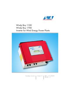
1 Sunny Boy SB 1100 and SB 1700 String Inverter for Photovoltaic PlantsInstallation Guide Version SB11_17-11:SE5006 IMEN-SB11_17 SMA Technologie AGTable of ContentsInstallation GuideSB11_17-11:SE5006 Page 3 Inhaltsverzeichnis1 Explanation of the Symbols Used .. 52 Foreword .. Group .. Usage.. of Documentation .. 83 Safety Instructions .. 94 Overview .. Description .. Dimensions .. 125 Installation Requirements.. Location Requirements .. Generator Requirements .. Voltage Grid (AC) .. 166 Installation .. the Device.. Installation.. the AC Output .. String (DC) Connection .. 317 Opening and Closing the Sunny Boy .. the Sunny Boy .. the Sunny Boy.
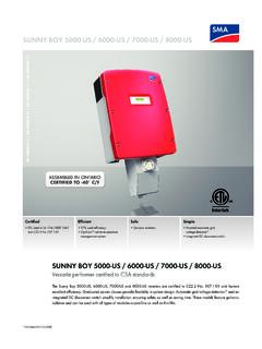
2 338 Technical Data .. PV Generator Connection Sunny Boy SB 1100 Grid Connection Sunny Boy SB 1100.. PV Generator Connection Sunny Boy SB 1700 37 Table of ContentsSMA Technologie AGPage 4SB11_17-11:SE5006 Installation Grid Connection Sunny Boy SB 1700.. Description .. Sunny Boy SB 1100 .. Sunny Boy SB 1700 .. Parameters .. of the operating Parameters .. Settings for Germany .. Parameter Settings .. Parameters .. Declaration of Conformity .. Grid Guard Certificate ..509 Replacing the Varistors .. 5110 Rating for a Line Circuit Breaker .. 5511 The Communication Interface .. of the Interface .. Jumper functions ..6112 Contact.. 63 SMA Technologie AGExplanation of the Symbols UsedInstallation GuideSB11_17-11:SE5006 Page 51 Explanation of the Symbols UsedTo ensure optimum use of this document, note the following explanation of the symbol indicates an symbol indicates a note which, if ignored, will make the procedure oroperation more symbol indicates a fact which, if not observed, could result in damageto components or represent a danger to persons.
3 Read these passagesespecially of the Symbols UsedSMA Technologie AGPage 6SB11_17-11:SE5006 Installation GuideSMA Technologie AGForewordInstallation GuideSB11_17-11:SE5006 Page 72 ForewordRefer to the operating manual for detailed information on troubleshooting andoperating the Sunny Boy. Sunny Design will assist you in the system design and checking of the String size for agiven type of Inverter . Further information on Sunny Design is available you require further information, please call the Sunny Boy Hotline: +49 (561) 95 22 - Target GroupThis installation guide is exclusively intended for qualified electricians and is intendedto assist with the speedy and correct installation and commissioning of the SMA SunnyBoy SB 1100 and Sunny Boy SB 1700 Appropriate UsageThe Sunny Boy is equipped with the SMA grid guard.
4 This is a type of automaticdisconnection device. This means that the Sunny Boy complies with the VDEW(Verband der Elektrizit tswirtschaft German Electricity Industry Association)regulations for the connection and parallel operation of power-generating systemsto the low-voltage grid of the energy supply company and with DIN VDE 0126-1-1, which forms part of these !The Sunny Boy may only be installed by trained specialists. The installermust be approved by the local energy supplier. Read this installationguide carefully. Ensure compliance with all prescribed safety regulations,the technical connection requirements of the local energy supplier andany other applicable !
5 The Sunny Boy is designed for operation in grid-connected PV of the Sunny Boy in any areas of application other than thosespecified in this documentation will lead to the loss of the right to allwarranty claims and may lead to a fault in the device. This includes,among other things, the operation at voltage sources without any currentlimit. When in doubt, contact Technologie AGPage 8SB11_17-11:SE5006 Installation Validity of DocumentationThe Sunny Boy SB 1100 and Sunny Boy SB 1700 are identical in construction and onlydiffer in their technical data. This documentation uses the terms Sunny Boy or inverterwhen referring to both device types. The device will be specified with its full name if theinformation only refers to that particular Technologie AGSafety InstructionsInstallation GuideSB11_17-11:SE5006 Page 93 Safety Instructions Warning!
6 Overvoltage!Check the system design using the SunnyDesign tool ( ) or by callingthe Sunny Boy Hotline. Overvoltages leadto the destruction of the Sunny ! High voltage!Work on the Sunny Boy with the cover removed must be carried out by aqualified electrician! High voltages are present in the device. Work is tobe carried out on the Sunny Boy only once the AC and DC voltages havebeen disconnected from the Sunny Boy, and once it has been ensured thatthe capacitors have been Sunny Boy must be disconnected from the grid and precautions mustbe taken to prevent the grid being accidentally reconnected. In addition,the connections to the PV generator must be isolating the AC and DC voltage, you must wait approximately 30minutes for the capacitors in the Sunny Boy to discharge.
7 Only then is itsafe to open the unit by removing the cover and make sure that novoltage is present in the ! Electrostatic charge!When working on the Sunny Boy and handling its assemblies, rememberto observe all ESD safety regulations. Electronic components aresusceptible to electrostatic charge. Discharge any electrostatic charge bytouching the grounded housing before handling any InstructionsSMA Technologie AGPage 10SB11_17-11:SE5006 Installation GuideSMA Technologie AGOverviewInstallation GuideSB11_17-11:SE5006 Page 114 Unit DescriptionThe following diagram gives a schematic overview of the various components andconnection points inside the Sunny Boy with the cover removed.
8 PV input plugs (DC), section feed-through for the optional Electronic Solar SwitchVaristors, section 9 Communication socket (RS232, RS485, NLM Piggy-Back, radio), section 11 Sunny DisplayOperating status LEDsCommunication jumperPE (protective earth) connecting cable for coverPlug socket (AC), section plug connection for grounding the cable shield for RS232 and RS485 communicationOverviewSMA Technologie AGPage 12SB11_17-11:SE5006 Installation External Dimensions214 mm295 mm434 mmSMA Technologie AGInstallation RequirementsInstallation GuideSB11_17-11:SE5006 Page 135 Installation RequirementsCheck that all of the requirements listed below are met before installing andcommissioning the Sunny Installation Location RequirementsThe Sunny Boy SB 1100 weighs 22 kg, the Sunny Boy SB 1700weighs 25 kg.
9 Take this weight into account when choosing theinstallation location and method of Sunny Boy should be installed in a place where it is notexposed to direct sunlight. An increased ambient temperature canreduce the yield of the PV Sunny Boy is designed to be mounted on a vertical wall. However, if absolutelynecessary, the Sunny Boy can be installed tilted back at a maximum angle of 45 .Vertical installation at eye-level is preferable for an optimum energy yield and maximumoperational comfort. If installing the unit outdoors, make sure that it is not slantingforwards. We advise against installing the unit in a horizontal position ambient temperature must not be outside the -25 C to+60 C / 25 kgInstall the Inverter vertically or tilting install the Inverter horizontally or so that it tilts RequirementsSMA Technologie AGPage 14SB11_17-11:SE5006 Installation GuideWhen choosing the installation location, be sure to observe the following:When choosing the installation location, ensure there is enough space for heat todissipate!
10 Under normal conditions, the following recommended values for the spaceto be kept clear around the Sunny Boy should be followed: Warning! High voltage! Unintentionally pulling out the DC plug connectors under load candamage the plugs and could result in personal injury! Install the SunnyBoy in such a way that it is not possible ( for children) to unplug theDC plug connector ! Risk of burns!The temperature of individual parts of the housing, in particular thetemperature of the heatsink and the components inside the Sunny Boy canreach more than 60 C. There is the danger of burn injury when theseparts are touched!Warning!Do not install the Sunny Boy on flammable construction materials, in areas where highly inflammable materials are stored, in potentially explosive environments!