Transcription of Super Slim Heavy - Dynamics Automation
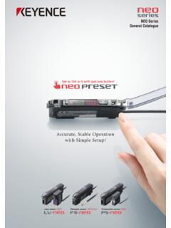
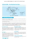
1 NEW Safety Light Curtain SL-V Series Maximum safety standard Type4 SIL3 Category4 PLe Super Super Heavy slim Duty You Will SEE the Difference! NEW Safety Relay NEW PC Configuration Terminal Software Standard Heavy duty SL-T11R SL-VH1S. Lightweight & Super slim Body Makes Compact Installation Possible Visible Safety Light Curtain Visible Safety Light Curtain SL-V Series Full Lineup Super slim Minimum detectable object 14 mm SL-VF Series World's first Highly-Visible Indicators Minimum detectable object 25 mm SL-VH Series Additional New Safety Equipment NEW. Exclusively for the SL-V Series Relay Terminal SL-T11R. 2. Designed for use in tough environments Visible Safety Light Curtain Super Heavy Duty Minimum detectable object 14 mm World's first Highly Visible NEW Indicators SL-VFM Series The SL-V Series meets IP67 standards without the need for any additional accessories Minimum detectable object 25 mm The SL-V Series conforms to IP65 and IP67 based on IEC/JIS standards SL-VHM Series No damage from shock This model can be used in places where workpieces often strike the unit.
2 NEW. NEW NEW. PC Configuration Software Interface Unit USB Cable SL-VH1S SL-V1UB OP-51580. (Include with the SL-V1UB). 3. New Version Information for All SL-V. Series Models With the new functions, it is no longer necessary to purchase an additional control unit. Functions like muting and beam axis intensity monitoring that used to be difficult or impossible, are now easy to setup using the software. As a result, on-site installation time will be greatly reduced. 4. Programmable Muting function Programmable Muting allows the user to customise what parts of the safety curtain are suspended. Up to three different clearance heights can be programmed so that the user can easily pass different height parts while maintaining maximum safety. Clearance height 1 Clearance height 2. (The height of the work piece : low) (The height of the work piece : high). Fixed Blanking function This function is used when an obstacle is always within the detection area.
3 It makes it possible to operate a safety light curtain normally even with an obstacle present. Floating Blanking function This function is used when an obstacle moves within the detection area. The output turns off only if the light is blocked in more optical axes than the set number. 5. The SL-VH1S PC configuration software Makes It Possible to Reduce The On-Site safety light curtain The SL-V Series Installation Time! Connection cable NEW Interface unit SL-V1UB. Required System Environment NEW USB cable OP-51580. (Include with the SL-V1UB). NEW SL-VH1S. The Configuration Software Makes it Possible to- Monitor received light Configure the Override function intensity of beam axes The SL-VH1S software can be used to adjust the time It gives the user a visual indication of limit of the Override function from the default 60. beam strength for alignment, seconds to as much as 15 minutes. troubleshooting, or initial setup. Configure the EDM function Precisely configure The EDM makes it possible to monitor external devices the Muting function such as contactors.
4 The SL-V configuration software It can be used to choose which beams (SL-VH1S) allows the user to select whether or not to use are used for Muting and Blanking the EDM function and to select permissible times for it. functions with a PC. Customise the Highly-Visible Indicators Configure the Interlock function It allows the operator to select how the Highly-Visible Easily configure how to reset the light curtain(Interlock Indicators spanning the whole curtain will light or flash and function) under the following two conditions. what colour they will be for different conditions. This helps the -Upon startup: Automatic or Manual user to see the current operating status of the safety light -After an obstruction: Automatic or Manual curtain. 6. Introducing the user-friendly safety relay 1. Quick 2. Replaceable 3. Dedicated Power Connector Relay Supply SL-T11R Type4 Safety Relay Terminal The SL-T11R combines all of the features necessary to build a Category 4 compatible safety circuit into a single unit.
5 This makes it possible to dramatically reduce the amount of time and labour required by complex circuit design processes. It also boasts quick connectors that simplify the wiring process involved in connecting the relay to the light curtain itself. The SL-T11R eliminates the need for specialised knowledge about safety circuits. Quick Connector Space-saving Space-saving design The safety light curtain is The SL-T11R case design ensures connected via a quick that the connectors do not extend connector, eliminating the outside of the unit's footprint, danger of wiring mistakes helping to save space inside and reducing the amount control panels. of time and labour required for wiring. Replaceable Relay The relay board (OP-84388) can be replaced without removing any wires which eliminates time loss and potential connection mistakes during board rewiring. Safety Relay Terminal *The terminal unit can also be removed separately. SL-U2 AC Power Supply SL-U2, dedicated power source with class 2 output In order to use the SL-V Series as a Type 4 light curtain, it is necessary to have a power supply that meets IEC/EN/UL61496-1 requirements.
6 The SL-U2. is a dedicated power supply unit that meets all of these requirements. The SL-U2 uses a direct connection, eliminating the need for external wiring. 7. For safety and efficiency in the workplace Introducing a safety light curtain completely focused on visibility SL-V. Quickly recognise the status of the safety light curtain 1 Visible/Identifiable Indicator Installation style that fits the setup with no dead zone 2 Edge-to-Edge Construction Reduce No. of parts and mounting processes 3 Built-in Safety Controller Function [EDM function, muting function]. 8. 1 Visible/Identifiable Indicator Quickly recognise the presence of a safety light curtain New Know Immediately Whether The Safety Light Curtain Is Active J Clear status indication By using the Visible/Identifiable Indicator, operators can immediately determine whether the safety light curtain is being used, thus preventing situations where the light is accidentally blocked.
7 Visible [ 1] Clear Status Indication The status of the safety light J During operation curtain can be easily Blocked determined by the blinking Normal light or Error or lighting. The cause can be [During mis- occurred emission] aligned easily identified if the safety beam curtain does not start up. axis Red flashing Green lights Red lights lights During normal operation, there is no The beam axes are misaligned or dirty, or An error (such as a malfunction in interruption in the detection zone. there is interruption in the detection zone. an external device) has occurred. J During startup Misaligned Wrong beam wiring axes Off or Red red light flashing lights (part or all). There is an error due to wrong The beam axes are misaligned, not wiring or similar problems. due to damage or a similar error. Visible [ 2 ] 3 Step Adjustment Easy Beam Axis Alignment Using the Visible Indicator, STEP 1 Align the top row STEP 2 Align the bottom row STEP 3 Fine-tune the rotational direction beam axis alignment can be The indicators at the top light up All of the indicators light red when All of the indicators light green when when the top beam axis is aligned.
8 The bottom beam axis is aligned. all of the beam axes are aligned. performed in just three steps. Fine-tune 9. Installation style that fits the setup 2 Edge-to-Edge construction Conventional NO DEAD ZONE. With the first beam axis placed DEAD Z. ONE. right along the edge and cables drawn to the side, detection can be performed along the entyre area. Since there is no need to install it outside of the sensing area in order to cover the dead zone, the light curtain can fit snugly into the setup. SL-V. DEAD. ZONE. NO DEAD ZONE Cable drawn to the side 1 Outside installation [Sticking out]. It sticks out from the Conventional setup and In order to cover the interferes top and bottom dead with zones, the light curtain operations. With the SL-V, is installed outside of the entrance. there is NO DEAD ZONE. 2 Inside installation Does not stick out [Creating dead zone]. No additional Preparing protection plate the needed Conventional protection Install an additional plate is protection plate annoying 3 Series connection [Creating dead zone] With the SL-V, there is NO DEAD ZONE.
9 Conventional Creates double dead Up to 3 units can be Cannot avoid dead zone zone connected in series 10. 3 Built-in Safety Controller Function Reduce No. of parts and mounting processes Direct link to an external device Compliance with Category 4 requirements without a Safety Relay Unit With a built-in external device monitoring (EDM) function, the requirements for category 4 can Shorten safety Reduce cost distance be fulfilled without a safety relay unit. The maximum capacity that can be controlled with the OSSD output is a current load up to 500 mA, thus allowing direct driving of external devices*. * External devices cannot be used if the input current exceeds 500 mA. J Conventional CATEGORY. Safety light curtain Safety relay unit External device (Contactor, etc.). 4. J SL-V. CATEGORY. Direct SL-V Series 24 VDC, 500 mA. [Advantage]. Reduce cost and shorten response time External device 4. Detect malfunctions on an external device (Contactor, etc.)
10 Built-in muting function Perform Muting without a Dedicated Controller The SL-V has built-in muting functions, so a safety control circuit can be constructed without a dedicated Reduce cost controller. Using the State Information Output, the SL-V status can be sent to a standard (non-safety) PLC. J Conventional Muting input Muting lamp Safety Muting relay unit unit External device Motor, etc. Safety light curtain (Contactor, etc.). J SL-V Muting input Muting lamp Direct [Advantage]. Reduce cost and the number of installation processes External device Motor, etc. SL-V Series (Contactor, etc.). Function to detect malfunctions on an external device 11. Improved upon the demands of electricity supervisors to make the safety light curtain easier to use Distinguish between safety output off and error off Separate Alert Output Many operators wanted a function that would not just simply turn the safety light curtain on or off, Safety output but instead clearly indicate the error*.