Transcription of Surface Footage Surface Footage Chart and Formula
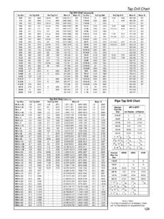
1 Surface Footage Surface Footage Chart and Formula Surface Footage Theory behind Surface Feet per Minute: 1. Every cutter has a Diameter 2. Diameter x (PI) = Distance cutter travels every revolution 3. Distance cutter travels every Revolution x 12 = Distance traveled in Feet.(SF). 4. Chart is Recommending how far your cutter should travel per minute in feet. (SFM). Theory behind Feed Rate Formula (inches): 1. It is Always calculated in Inches per Tooth (in/tooth). 2. For every time a cutter goes around how far should the cutter advance into the material Per Tooth. 3. The Chart is Recommending a Chip Load per Tooth depending on cutter diameter and depth of cut. 4. Chip Load per Tooth x Number of teeth = (Inches per Revolution). The following Chart is Recommended Surface Footage for standard 4-Flute styled endmills. For aluminums, start somewhere in the middle.
2 For steels start on the bottom side and work your way up. Always use manufacturers recommended Surface Footage for tooling where applicable. 126. Surface Footage RPM. SFM X / Cutter Diameter = RPM. Feed Rate RPM X Chip Load(FPT) X Number of Teeth = Feed Rate FPT for Material SFM FPT for Endmills HSS Drill HSS Carbide HSS Carbide 1/16-3/4 . 1018 CRS 125 350 .. 6061-T6. 250-800 800-1300 .. ALUM. 11L17 170 415 .. 4140 70 300 .. A2 TOOL. 50 250 .. STEEL. P20 MOLD. 70 320 .. STEEL. 303 SS 100 300 .. 304/316 SS 60 230 .. 416 SS 110 335 .. 440C SS 50 205 .. 17-4 SS 55 220 .. Delrin 450 800-1300 .. Example: 1/2 4-Flute Endmill cutting 1018 CRS. 350 x / .500 = 2674 RPM. 2674 x .002 x 4 = in/min FPT = Feed Per Tooth 127.