Transcription of SURFACE-MOUNT CERAMIC MULTILAYER …
1 Product Specification May 5, 2017 DATA SHEET SURFACE-MOUNT CERAMIC MULTILAYER capacitors 01005 NP0/X5R/X7R 4 V TO 25 V pF to 470 nF RoHS compliant & Halogen Free May. 5, 2017 SURFACE-MOUNT CERAMIC MULTILAYER capacitors 2 11 Product specification 01005 NP0/X5RX7R 4V to 25V ORDERING INFORMATION - GLOBAL PART NUMBER, PHYCOMP CTC & 12NC All part numbers are identified by the series, size, tolerance, TC material, packing style, voltage, process code, termination and capacitance value. YYAAGGEEOO BBRRAANNDD oorrddeerriinngg ccooddee GLOBAL PART NUMBER (PREFERRED) CC XXXX X X XXX X B X XXX (1) (2) (3) (4) (5) (6) (7) (1) SIZE INCH BASED (METRIC) 0100(0402) (2) TOLERANCE B = C = D = J = 5% K = 10% M = 20% (3) PACKING STYLE R = Paper/PE taping reel.
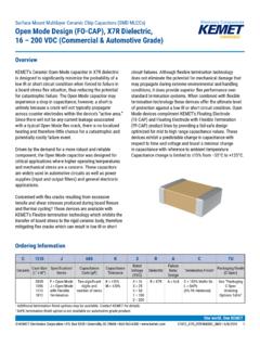
2 Reel 7 inch (4) TC MATERIAL NPO X5R X7R (5) RATED VOLTAGE 4 = 4 V 5 = V 6 = 10 V 7 = 16 V 8 = 25 V (6) PROCESS N = NP0 B = Class 2 MLCC (7) CAPACITANCE VALUE 2 significant digits+number of zeros The 3rd digit signifies the multiplying factor, and letter R is decimal point Example: 121 = 12 x 101 = 120 pF SCOPE This specification describes 01005 NP0/X5R series chip capacitors with lead-free terminations. APPLICATIONS Mobile Module FEATURES Supplied in tape on reel Nickel-barrier end termination RoHS compliant Halogen Free compliant May. 5, 2017 SURFACE-MOUNT CERAMIC MULTILAYER capacitors 3 11 Product specification 01005 NP0/X5RX7R 4V to 25V CONSTRUCTION The capacitor consists of a rectangular block of CERAMIC dielectric in which a number of interleaved metal electrodes are contained.
3 This structure gives rise to a high capacitance per unit volume. The inner electrodes are connected to the two end terminations and finally covered with a layer of plated tin (NiSn). The terminations are lead-free. A cross section of the structure is shown in Fig. 1 Surface mounted MULTILAYER CERAMIC capacitor construction TYPE L1 (mm) W (mm) T (mm) L2 / L3 (mm) L4 (mm) min. max. min. 01005 Table 1 For outlines see fig. 2 DIMENSION OOUUTTLLIINNEESS For dimension see Table 1 Fig. 2 Surface mounted MULTILAYER CERAMIC capacitor dimension May.
4 5, 2017 SURFACE-MOUNT CERAMIC MULTILAYER capacitors 4 11 Product specification 01005 NP0/X5RX7R 4V to 25V CAPACITANCE RANGE & THICKNESS Table 2 01005 Sizes CAP. NP0 16 V / 25 V pF pF pF pF pF pF pF pF pF pF pF pF pF pF pF pF pF pF 10 pF 12 pF 15 pF 18 pF 22 pF 27 pF 33 pF 39 pF 47 pF 56 pF 68 pF 82 pF 100 pF Tape width 8 mm CAP. X7R / 10V 16V 100 pF 150 pF 220 pF 330 pF 470 pF 680 pF 1 000 pF nF nF 10 nF 22nF 47 nF 100 nF 220 nF Tape width 8 mm CAP.
5 X5R 4V 10V 100 pF 150 pF 220 pF 330 pF 470 pF 680 pF 1 000 pF nF nF 10 nF 22nF 47 nF 100 nF 220 nF 470 nF Tape width 8 mm May. 5, 2017 SURFACE-MOUNT CERAMIC MULTILAYER capacitors 5 11 Product specification 01005 NP0/X5RX7R 4V to 25V ELECTRICAL CHARACTERISTICS NNPP00//XX55RR DDIIEELLEECCTTRRIICC CCAAPPAACCIITTOORRSS;; NNIISSNN TTEERRMMIINNAATTIIOONNSS Unless otherwise specified, all test and measurements shall be made under standard atmospheric conditions for testing as given in of IEC 60068-1: - Temperature: 15 C to 35 C - Relative humidity: 25% to 75% - Air pressure: 86 kPa to 106 kPa Before the measurements are made, the capacitor shall be stored at the measuring temperature for a time sufficient to allow the entire capacitor to reach this temperature.
6 The period as prescribed for recovery at the end of a test is normally sufficient for this purpose. Table 3 THICKNESS CLASSES AND PACKING QUANTITY SIZE CODE THICKNESS CLASSIFICATION TAPE WIDTH QUANTITY PER REEL 180 MM / 7 INCH 330 MM / 13 INCH QUANTITY PER BULK CASE Paper/PE Blister Paper/ Blister 01005 mm 8 mm 20,000 --- --- --- --- Table 4 DESCRIPTION VALUE Capacitance range pF to 470 nF Capacitance tolerance C< 10 pF , , NP0 C 10 pF 5%, 10% X5R / X7R 10%, 20% Dissipation factor ( ) NP0 C < 30 pF 1 / ( 400 + 20C ) C 30 pF % X5R / X7R 10 % Insulation resistance after 1 minute at Ur (DC)
7 Rins 10 G or Rins C 500 F whichever is less X5R/X7R > 10nF: Rins x C 50 F Maximum capacitance change as a function of temperature (temperature characteristic/coefficient): NP0 30 ppm/ C X5R / X7R 15% Operating temperature range: NP0 55 C to +125 C X5R 55 C to +85 C X7R 55 C to +125 C May. 5, 2017 SURFACE-MOUNT CERAMIC MULTILAYER capacitors 6 11 Product specification 01005 NP0/X5RX7R 4V to 25V SOLDERING RECOMMENDATION Table 5 SOLDERING METHOD SIZE 01005 Reflow Reflow only Reflow/Wave --- TEST TEST METHOD PROCEDURE REQUIREMENTS Mounting IEC 60384-21/22 The capacitors may be mounted on printed-circuit boards or CERAMIC substrates No visible damage Visual Inspection and Dimension Check Any applicable method using 10 magnification In accordance with specification Capacitance Class 1.
8 F = 1 MHz for C 1 nF, measuring at voltage 1 Vrms at 20 C f = 1 KHz for C > 1 nF, measuring at voltage 1 Vrms at 20 C Class 2: C 1 nF f = 1 KHz, measuring at voltage 1 Vrms at 20 C C > 1 nF f = 1 KHz, rated voltage V, measuring at voltage Vrms at 20 C f = 1 KHz, rated voltage > 10 V, measuring at voltage 1 Vrms at 20 C Within specified tolerance Dissipation Factor ( ) Class 1: f = 1 MHz for C 1 nF , measuring at voltage 1 Vrms at 20 C f = 1 KHz for C > 1 nF, measuring at voltage 1 Vrms at 20 C Class 2: C 1 nF f = 1 KHz, measuring at voltage 1 Vrms at 20 C C > 1 nF f = 1 KHz, rated voltage V, measuring at voltage Vrms at 20 C f = 1 KHz, rated voltage > 10 V, measuring at voltage 1 Vrms at 20 C In accordance with specification Insulation Resistance At Ur (DC) for 1 minute In accordance with specification TESTS AND REQUIREMENTS Table 6 Test procedures and requirements May.
9 5, 2017 SURFACE-MOUNT CERAMIC MULTILAYER capacitors 7 11 Product specification 01005 NP0/X5RX7R 4V to 25V TEST TEST METHOD PROCEDURE REQUIREMENTS Temperature coefficient Capacitance shall be measured by the steps shown in the following table. The capacitance change should be measured after 5 min at each specified temperature stage. Step Temperature( C) a 25 2 b Lower temperature 3 C c 25 2 d Upper Temperature 2 C e 25 2 (1) Class I Temperature Coefficient shall be calculated from the formula as below Temp, Coefficient =610T xC1C1-C2 [ppm/ C] C1: Capacitance at step c C2: Capacitance at 125 C T: 100 C(=125 C-25 C) Measuring Voltage: to 5 Vrms (2) Class II Capacitance Change shall be calculated from the formula as below C = C1C1-C2 x 100% C1: Capacitance at step c C2: Capacitance at step b or d C/C Class1 (NP0): 30ppm Class 2: (X7R/X5R): 15% In case of applying voltage, the capacitance change should be measured after 1 more min.
10 With applying voltage in equilibration of each temp. stage. CC0100 MRX5R4(5)BB104(224): Adhesion IEC 60384-21/22 A force applied for 10 seconds to the line joining the terminations and in a plane parallel to the substrate Force size 01005 : 1N Bending Strength Mounting in accordance with IEC 60384-22 paragraph No visible damage Conditions: bending 1 mm at a rate of 1 mm/s, radius jig 5 mm C/C Class 1 (NP0): within 1% or pF, whichever is greater Class2 (X5R/X7R): 10% May. 5, 2017 SURFACE-MOUNT CERAMIC MULTILAYER capacitors 8 11 Product specification 01005 NP0/X5RX7R 4V to 25V TEST TEST METHOD PROCEDURE REQUIREMENTS Resistance to Soldering Heat Precondition: 150 +0/ 10 C for 1 hour, then keep for 24 1 hours at room temperature Preheating: 120 C to 150 C for 1 minute and 170 C to 200 C for 1 minute.