Transcription of Surface Mount Multilayer Ceramic Chip Capacitors (SMD ...
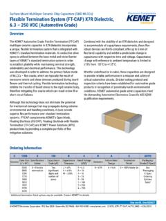
1 1 KEMET Electronics Corporation KEMET Tower One East Broward Boulevard C1013_X7R_FT-CAP_SMD 3/10/2021 Fort Lauderdale, FL 33301 USA 954-766-2800 Into TomorrowOverviewThe KEMET Flexible Termination (FT-CAP) Multilayer Ceramic capacitor in X7R dielectric incorporates a unique, flexible termination system that is integrated with the KEMET standard termination materials. A conductive silver epoxy is utilized between the base metal and nickel barrier layers of KEMET s standard termination system in order to establish pliability, while maintaining terminal strength, solderability and electrical performance. This technology was developed in order to address the primary failure mode of MLCCs flex cracks, which are typically the result of excessive tensile and shear stresses produced during board flexure and thermal cycling.
2 Flexible termination technology inhibits the transfer of board stress to the rigid Ceramic body, therefore mitigating flex cracks which can result in low IR or short circuit failures. Although this technology does not eliminate the potential for mechanical damage that may propagate during extreme environmental and handling conditions, it does provide superior flex performance over standard termination systems. FT-CAP complements the KEMET Open Mode, Floating Electrode (FE-CAP), Floating Electrode with Flexible Termination (FF-CAP) and KEMET Power Solutions (KPS) product lines by providing a complete portfolio of flex mitigation solutions.
3 Combined with the stability of an X7R dielectric and designed to accommodate all capacitance requirements, these flex-robust devices are RoHS-compliant, offer up to 5 mm of flex-bend capability and exhibit a predictable change in capacitance with respect to time and voltage. Capacitance change with reference to ambient temperature is limited to 15% from 55 C to +125 C. In addition to commercial grade, automotive grade devices are available which meet the demanding Automotive Electronics Council's AEC Q200 qualification Mount Multilayer Ceramic Chip Capacitors (SMD MLCCs)Flexible Termination system (FT-CAP), X7R Dielectric, 250 VDC (Commercial Grade) ordering InformationC1206X106K4 RACTUC eramicCase Size (L" x W")Specification/SeriesCapacitance Code (pF)Capacitance ToleranceRated Voltage (VDC)DielectricFailure Rate/ DesignTermination Finish1 Packaging/Grade (C-Spec)
4 2060308051206121018081812182522202225X = Flexible terminationTwo significant digits and number of zerosJ = 5%K = 10%M = 20%9 = = 104 = 163 = 255 = 501 = 1002 = 200A = 250R = X7RA = N/A C = 100% Matte SnL = SnPb (5% Pb minimum)See "Packaging C-Spec ordering Options Table"1 Additional termination finish options may be available. Contact KEMET for details. 2 KEMET Electronics Corporation KEMET Tower One East Broward Boulevard C1013_X7R_FT-CAP_SMD 3/10/2021 Fort Lauderdale, FL 33301 USA 954-766-2800 Mount Multilayer Ceramic Chip Capacitors (SMD MLCCs)Flexible Termination system (FT-CAP), X7R Dielectric, 250 VDC (Commercial Grade)Packaging C-Spec ordering Options TablePackaging Type1 Packaging/Grade ordering Code (C-Spec)Bulk Bag/UnmarkedNot required (Blank)7" Reel/UnmarkedTU13" Reel/Unmarked7411 (EIA 0603 and smaller case sizes)7210 (EIA 0805 and larger case sizes)7" Reel/MarkedTM13" Reel/Marked7040 (EIA 0603)7215 (EIA 0805 and larger case sizes)
5 7" Reel/Unmarked/2 mm pitch2708113" Reel/Unmarked/2 mm pitch270821 Default packaging is "Bulk Bag." An ordering code C-Spec is not required for "Bulk Bag" The terms "Marked" and "Unmarked" pertain to laser marking option of Capacitors . All packaging options labeled as "Unmarked" will contain Capacitors that have not been laser marked. Please contact KEMET if you require a laser marked option. For more information see "Capacitor Marking."2 The 2 mm pitch option allows for double the packaging quantity of Capacitors on a given reel size. This option is limited to EIA 0603 (1608 metric) case size devices. For more information regarding 2 mm pitch option see "Tape & Reel Packaging Information.
6 "Benefits 55 C to +125 C operating temperature range Superior flex performance (up to 5 mm) High capacitance flex mitigation Lead (Pb)-free, RoHS and REACH compliant EIA 0603, 0805, 1206, 1210, 1808, 1812, 1825, 2220, and 2225 case sizes DC voltage ratings of V, 10 V, 16 V, 25 V, 50 V, 100 V, 200 V, and 250 V Capacitance offerings ranging from 180 pF to 22 F Available capacitance tolerances of 5%, 10%, and 20% Automotive (AEC-Q200) grade available Non-polar device, minimizing installation concerns 100% pure matte tin-plated termination finish allowing for excellent solderability SnPb termination finish option available upon request (5% Pb minimum)ApplicationsTypical applications include circuits with a direct battery or power source connection, critical and safety relevant circuits without (integrated) current limitation and any application that is subject to high levels of board flexure or temperature cycling.
7 Examples include raw power input side filtering (power plane/bus), high current applications (automobile battery line) and circuits that cannot be fused to open. Markets include consumer, medical, industrial (power supply), automotive, aerospace and KEMET Electronics Corporation KEMET Tower One East Broward Boulevard C1013_X7R_FT-CAP_SMD 3/10/2021 Fort Lauderdale, FL 33301 USA 954-766-2800 Mount Multilayer Ceramic Chip Capacitors (SMD MLCCs)Flexible Termination system (FT-CAP), X7R Dielectric, 250 VDC (Commercial Grade)Dimensions Millimeters (Inches) L B W STEIA Size CodeMetric Size CodeL LengthW WidthT ThicknessB BandwidthSSeparation MinimumMounting ( ) ( ) ( ) ( )See Table 2 for ( ) ( ) ( )Solder wave or Solder ( ) ( ) ( ) ( ) ( ) ( )
8 ( ) ( ) ( ) ( ) ( ) ( ) ( ) ( ) ( ) ( ) ( ) ( ) ( )Solder reflow ( ) ( ) ( ) ( ) ( ) ( )181245324 .5 0 ( 8) ( ) ( ) ( ) ( ) ( )182545644 .6 0 ( 1) ( ) ( ) ( ) ( ) ( ) ( ) ( )5 .0 0 ( 7 ) ( ) ( ) ( ) ( ) ( ) ( ) ( ) ( ) ( )1 For capacitance values F add ( ) to length tolerance For capacitance values F or F add ( ) to length tolerance KEMET Electronics Corporation KEMET Tower One East Broward Boulevard C1013_X7R_FT-CAP_SMD 3/10/2021 Fort Lauderdale, FL 33301 USA 954-766-2800 Mount Multilayer Ceramic Chip Capacitors (SMD MLCCs)Flexible Termination system (FT-CAP), X7R Dielectric, 250 VDC (Commercial Grade)Qualification/CertificationCommerc ial grade products are subject to internal qualification.
9 Details regarding test methods and conditions are referenced in Table 4, Performance & ComplianceLead (Pb)-free, RoHS, and REACH compliant without exemptions (excluding SnPb termination finish option.)Electrical Parameters/CharacteristicsItemParameters /CharacteristicsOperating Temperature Range 55 C to +125 C Capacitance Change with Reference to +25 C and 0 VDC Applied (TCC) 15%1 Aging Rate (Maximum % Capacitance Loss/Decade Hour) Withstanding Voltage (DWV) 250% of rated voltage (5 1 seconds and charge/discharge not exceeding 50 mA)3 Dissipation Factor (DF) Maximum Limit at 25 CSee Dissipation Factor Limit table4 Insulation Resistance (IR) Minimum Limit at 25 CSee Insulation Resistance Limit table (Rated voltage applied for 120 5 seconds at 25 C)1 Regarding Aging Rate.
10 Capacitance measurements (including tolerance) are indexed to a referee time of 48 or 1,000 hours. Please refer to a part number specific datasheet for referee time details2 DWV is the voltage a capacitor can withstand (survive) for a short period of time. It exceeds the nominal and continuous working voltage of the Capacitance and dissipation factor (DF) measured under the following conditions: 1 kHz 50 Hz and Vrms if capacitance 10 F 120 Hz 10 Hz and Vrms if capacitance > 10 F4 To obtain IR limit, divide M F value by the capacitance and compare to G limit. Select the lower of the two : When measuring capacitance it is important to ensure the set voltage level is held constant.