Transcription of SYNCHRONOUS MEDIUM VOLTAGE CIRCUIT BREAKERS: …
1 SYNCHRONOUS MEDIUM VOLTAGE CIRCUIT BREAKERS: abb solution BASED ON MAGNETIC. DRIVE AND ELECTRONIC CONTROL. Carlo Cereda Carlo Gemme Christian Reuber ABB SACE ABB Ricerca SpA ABB Calor Emag Mittelspannung Corporate Research Italy GmbH. Via Friuli, 4 Edison, 50 Bahnstra e 39-47. I-24044 Dalmine (Italy) I-20099 Sesto S. Giovanni (Italy) D-40832 Ratingen (Germany). Tel. +39 035 395 -922; FAX -869 Tel. +39 02 262 -152; FAX -188 Tel. +49 2102 12 -1544; FAX -1933. ABSTRACT ELECTROMECHANICAL SYSTEM. To obtain a SCB with a spring based mechanism, the The present paper describes the principles and the cus- manufacturer has to rely on the predictable behaviour of tomer-value of SYNCHRONOUS MEDIUM - VOLTAGE CIRCUIT - the opening/closing operation.
2 This requires a mechanism breakers, available with SF6 and vacuum interrupters. with a high excess energy, having low dependence on wear These CIRCUIT -breakers have three individually driven and friction. It is critical to keep the environmental influ- poles enabling complex SYNCHRONOUS switching strategies ences under control. This demands extensive laboratory that can be adapted to various loads and network configu- tests, leading finally to algorithms which have to be im- rations. The use of magnetic actuators for the drives takes plemented in an electronic control. advantage of the mechanical simplicity and the opportu- This alone does not assure a reliable behaviour, because nity of controlling the motion by changing the current in the motion of the spring based mechanism cannot be influ- the coils during the operation.
3 This leads to a very high enced after being released. The magnetic actuator, how- reliability. Considerable cost reduction in the network can ever, provides the opportunity to implement the adaptive be achieved thanks to the reduction of switching tran- algorithm into a closed-loop control. This enables the sients. control of the motion to compensate for disturbing influ- Acronyms ences coming from temperature, ageing, etc., which guar- antees the long term stability of the operation time. CB: CIRCUIT breaker SCB: SYNCHRONOUS CB. CE: Control Electronic MA: Magnetic Actuator MEDIUM VOLTAGE CBs nowadays consist usually of three poles, that are mechanically connected, and one drive.
4 The INTRODUCTION drive can be of mechanical spring type or an electromag- Since 1997, ABB has introduced in the market a new netic actuator. For a really controlled switching, that is not series of MEDIUM VOLTAGE CBs having a magnetic drive limited to certain applications, an individual drive for each instead of a spring based mechanism [1]. This solution pole is required. With a magnetic actuator, this is much immediately proved much more reliable than the spring easier to achieve than with a mechanical drive. based one. Following this successful development, ABB is now developing a new controlled switching technology which will enable the user to carry out closing and open- ing operations synchronised with the power network.
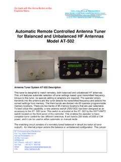
5 SYNCHRONOUS or point on the wave switching is a well- known concept [2]. In particular, it has been used in HV. applications to avoid or reduce switching transients and associated disturbances on the power network. Compared with conventional switching equipment, the SCB will: reduce transient stresses on network components improve the network power quality. enhance the electrical life & performance of the CB. enable to simplify the design of the network and to reduce the costs of the overall system. Figure 1: Section of the operating mechanism and pole part of the vacuum CIRCUIT - breaker 1 Lever shaft 5 Plunger 2 Proximity sensors 6 Opening coil 3 Closing coil 7 Emergency manual opening 4 Permanent magnets Furthermore, the repeatability of a magnetic drive is much better due to the lower number of mechanical parts being involved.
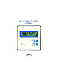
6 Figure 1 shows the simple mechanical structure of the vacuum CB: the pole is connected with the actuator via a lever shaft. The SF6 CB (figure 2) has a similar mechani- cal structure: the actuator turns a shaft that leads into the SF6 compartment of the pole. Inside the pole, this rota- tional movement is transformed into a linear movement and drives the moving contact. These principles are proven for non-synchronised breakers , where one actuator drives all three poles in parallel. Figure 4: Arrangement of actuators and poles of the vacuum SCB. Network synchronism A SCB is a CB that is able to carry out operations that are SYNCHRONOUS with the network signals, VOLTAGE or current, disregarding when the starting signal is given, either manually or by a remote control.
7 Figure 5: Example of SYNCHRONOUS operation Figure 5 shows how a SCB should behave during a closing operation: The solid line indicates the asynchronous closing signal given to the CB by the user or the control- Figure 2: Section of the operating mechanism of the SF6 CB protection systems. The dashed line shows the closing signal given by the CE to the actuator, synchronised with the VOLTAGE sig- Pole 6. Capacitors 4. 2. Actuator AM 800 Network VOLTAGE Transmission [kV]. -2. Structure -4. -6. 0 10 20 30 40 50 60 70 80 90. Figure 3: Arrangement of actuators and poles of the SF6 SCB Time [ms].
8 Operating time The arrangement of individually driven poles is shown in Synchronizing delay figure 3 for the SF6 CB and in figure 4 for the vacuum nal or current signal. CB. In comparison to a mechanical drive, this can be done The dotted line shows the closing instant at zero volt- with magnetic actuators in a rather simple way, leading to age of the SCB. a compact design. The SF6 CB is based on H BreaiKing poles manufactured by ABB SACE TMS, while the vac- The CE has the task to keep the operation time as much as uum CB is based on VM1 poles, where the vacuum inter- possible constant.
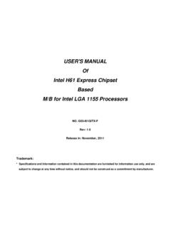
9 To do this it must have both an auto rupters are cast in epoxy-resin, manufactured by ABB adaptation mechanism and a real time close loop control. Calor Emag Mittelspannung GmbH. In this way it is able to keep the specified tolerances, even at different environmental temperature, capacitor charge and all the other relevant parameters. The CE is able to compensate automatically for the contact wear so as to always keep the right closing or opening instant. Magnetic Ac- tuator Switching CB time tolerance x The basic property of the SCB is to carry out operations in Iopen Iclose a highly reliable, pre-defined time, to guarantee during its service life the expected transient reduction.
10 Switching Unit The switching time tolerance of the described CB has the following maximum values: 1 ms for the closing operation, Control Unit 2 ms for the opening operation. While the second value is mainly important (but not only) Signal Processor & Timing Controller for the CB producer, the first one involves the tolerance in the closing operation which, according to the literature, is Operation Command defined as the minimum value required for an equal or better behaviour in terms of closing transient, with the standard means (see table 2) to reduce them [3]. Figure 7: Block diagram of the SCB.