Transcription of Synthesis Techniques - nyu.edu
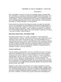
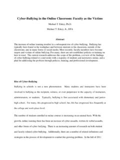
1 Synthesis Techniques Juan P Bello Synthesis It implies the artificial construction of a complex body by combining its elements. Complex body: acoustic signal (sound). Elements: parameters and/or basic signals . Synthesis Model / representation Sound Motivations: Reproduce existing sounds Reproduce the physical process of sound generation Generate new pleasant sounds Control/explore timbre How can I generate new sounds? Trigger Envelope Pitch vibrato Cutoff freq Oscillator Filter Sound Gain Networks of basic elements Synthesis Techniques Two main types: linear and non-linear Additive Synthesis It is based on the idea that complex waveforms can be created by the addition of simpler ones.
2 It is a linear technique, do not create frequency components that were not explicitly contained in the original waveforms Commonly, these simpler signals are sinusoids (sines or cosines). with time-varying parameters, according to Fourier's theory: Amp1(t). Freq1(t). Amp2(t). Freq2(t). s (t ) = ! Ai sin (2#f i t + " i ). i =0. AmpN(t). FreqN(t). Additive Synthesis : A Pipe Organ Additive Synthesis Square wave: only odd harmonics. Amplitude of the nth harmonic = 1/n Time-varying sounds According to Fourier, all sounds can be described and reproduced with additive Synthesis .
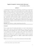
3 Even impulse-like components can be represented by using a short-lived sinusoid with infinite amplitude. Amp1(t) Amp Freq Freq1(t). Amp2(t) Amp Freq Freq2(t) . AmpN(t) Amp Freq FreqN(t). Additive Synthesis is very general (perhaps the most versatile). Control data hungry: large number of parameters are required to reproduce realistic sounds Examples orig det stoch SMS trans flute guitar water Subtractive Synthesis Is another linear technique based on the idea that sounds can be generated from subtracting (filtering out) components from a very rich signal ( noise, square wave).
4 Parameters Gain A Sound Complex f Waveform Filter Amplifier Its simplicity made it very popular for the design of analog synthesisers ( Moog). The human speech system The vocal chords act as an oscillator, the mouth/nose cavities, tongue and throat as filters We can shape a tonal sound ( oooh' vs aaah'), we can whiten the signal ( sssshhh'), we can produce pink noise by removing high frequencies Source-Filter model Subtractive Synthesis can be seen as a excitation-resonator or source-filter model The resonator or filter shapes the spectrum, defines the spectral envelope Source-Filter model Whitening of the signal Transformations Envelope estimation Analysis Processing Synthesis Amplitude modulation Non-linear technique, results on the creation of frequencies which are not produced by the oscillators.
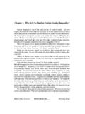
5 In AM the amplitude of the carrier wave is varied in direct proportion to that of a modulating signal. Ampm(t) Ampc(t). Freqm(t). Freqc(t). modulator carrier Bipolar -> Ring modulation Unipolar -> Amplitude modulation bipolar unipolar Ring Modulation Let us define the carrier signal as: c(t ) = Ac cos(!c t ). And the (bipolar) modulator signal as: m(t ) = Am cos(!mt ). The Ring modulated signal can be expressed as: s (t ) = Ac cos(!c t )" Am cos(!mt ). Which can be re-written as: Ac Am s(t) =. 2. [ ]. cos([" c # " m ] t ) + cos([" c + " m ] t ).
6 S(t) presents two sidebands at frequencies: c - m and c + m ! Ring Modulation fc - fm fc + fm amp fc freq Amplitude Modulation Let us define the carrier signal as: c(t ) = cos(!c t ). And the (unipolar) modulator signal as: m(t ) = Ac + Am cos(!mt ). The amplitude modulated signal can be expressed as: s (t ) = [Ac + Am cos(!mt )]cos(!c t ). Which can be re-written as: Am s(t) = Ac cos(" c t ) +. 2. [ ]. cos([" c # " m ] t ) + cos([" c + " m ] t ). s(t) presents components at frequencies: c , c - m and c + m ! Modulation index In modulation Techniques a modulation index is usually defined such that it indicates how much the modulated variable varies around its original value.
7 Am For AM this quantity is also known as modulation depth: ! =. Ac If = then the carrier's amplitude varies by 50% around its unmodulated level. For = 1 it varies by 100%. > 1 causes distortion and is usually avoided C/M frequency ratio Lets define the carrier to modulator frequency ratio c/m (= c /. m) for a pitched signal m(t). If c/m is an integer n, then c, and all present frequencies, are multiples of m (which will become the fundamental). If c/m = 1/n, then c will be the fundamental When c/m deviates from n or 1/n (or more generally, from a ratio of integers), then the output frequencies becomes more inharmonic Example of C/M frequency variation Frequency Modulation Frequency modulation (FM) is a form of modulation in which the frequency of a carrier wave is varied in direct proportion to the amplitude variation of a modulating signal.
8 Ampc(t). Ampm(t). Freqm(t) Freqc(t). modulator carrier When the frequency modulation produces a variation of less than 20Hz this results on a vibrato. Frequency Modulation Let us define the carrier signal as: c(t) = cos(" c t). And the modulator signal as: m(t) = " sin(# m t). The Frequency modulated signal can be expressed as: ! s (t ) = cos(!c t + " sin (!mt )). ! This can be re-written as %. s(t) = & J (" )cos[(#. k c + k# m ) t ]. k=$%. Frequency Modulation If 0 then the FM spectrum contains infinite sidebands at positions c k m. The amplitudes of each pair of sidebands are given by the Jk coefficients which are functions Jk of.
9 K Modulation index As in AM we define a FM modulation index that controls the modulation depth. In FM Synthesis this index is equal to , the amplitude of the modulator and is directly proportional to f. As we have seen the value of determines the amplitude of the sidebands of the FM spectrum Furthermore the amplitude decreases with the order k. Thus, although theoretically the number of sidebands is infinite, in practice their amplitude makes them inaudible for higher orders. The number of audible sidebands is a function of , and is approximated by 2 +1.
10 Thus the bandwidth increases with the amplitude of m(t), like in some real instruments C/M frequency ratio The ratio between the carrier and modulator frequencies c/m is relevant to define the (in)harmonic characteristic of s(t). The sound is pitched (harmonic) if c/m is a ratio of positive integers: c / m = Nc / Nm for fc = 800 Hz and fm = 200 Hz, we have sidebands at 600Hz and 1kHz, 400Hz and , 200Hz and , etc Thus the fundamental frequency of the harmonic spectrum responds to: f0 = fc / Nc = fm / Nm If c/m is not rational an inharmonic spectrum is produced If f0 is below the auditory range, the sound will not be perceived as having definitive pitch.