Transcription of SYSTEM DESIGN PROCESS PLANT PIPING OVERVIEW OF
1 1 OVERVIEW OFPROCESS PLANT PIPINGSYSTEM DESIGNBy: Vincent A. CarucciCarmagen Engineering, SystemPiping SYSTEM : conveys fluid betweenlocationsPiping SYSTEM includes: Pipe Fittings ( elbows, reducers, branch connections, etc.) Flanges, gaskets, bolting Valves Pipe supports3 ASME DESIGN Materials Fabrication Petroleum refineries Chemical plants Pharmaceutical plants Textile plants Paper plants Semiconductorplants Cryogenic plants Erection Inspection Testing Provides requirements for: For PROCESS plants including4 Scope of ASME PIPING and PIPING components, all fluidservices: Raw, intermediate, and finished chemicals Petroleum products Gas, steam, air, and water Fluidized solids Refrigerants Cryogenic fluids Interconnections within packaged equipment Scope exclusions specified5 Strength Yield and Tensile Strength Creep Strength Fatigue Strength Alloy Content Material Grain size Steel Production Process6 Stress - Strain DiagramSABCE7 Corrosion Resistance Deterioration of metal by chemical orelectrochemical action Most important factor to consider Corrosion allowance added thickness Alloying increases corrosion resistance8 PIPING SYSTEM CorrosionGeneral orUniformCorrosionUniform metal loss.
2 May be combined with erosion ifhigh-velocity fluids, or moving fluids metal loss randomly located on materialsurface. Occurs most often in stagnant areas or areas oflow-flow when two dissimilar metals contact each other incorrosive electrolytic environment. Anodic metal developsdeep pits or grooves as current flows from it to Corrosion Localized corrosion similar to pitting. Occurs at placessuch as gaskets, lap joints, and bolts where CorrosionOccurs when different concentration of either a corrosivefluid or dissolved oxygen contacts areas of same associated with stagnant in cast iron exposed to salt water or weak iron in cast iron, and leaves graphite in is extremely soft material with no metal Toughness Energy necessary to initiate andpropagate a crack Decreases as temperature decreases Factors affecting fracture toughnessinclude: Chemical composition or alloying elements Heat treatment Grain size10 Fabricability Ease of construction Material must be weldable Common shapes and forms include.
3 Seamless pipe Plate welded pipe Wrought or forged elbows, tees, reducers,crosses Forged flanges, couplings, valves Cast valves11 Availability and Cost Consider economics Compare acceptable options based on: Availability Relative cost12 Pipe Fittings Produce change in geometry Modify flow direction Bring pipes together Alter pipe diameter Terminate pipe13 Elbow and ReturnFigure 45 180 Return14 TeeFigure Outlet TeeCross Tee15 ReducerFigure Eccentric16 Welding Outlet FittingFigure Stub EndFigure square cornerRREnlarged Section of Lap19 Typical Flange AssemblyFigure of FlangeAttachment and FacingFlange Attachment TypesFlange Facing TypesThreaded FlangesFlat FacedSocket-Welded FlangesBlind FlangesRaised FaceSlip-On FlangesLapped FlangesRing JointWeld Neck FlangesTable Facing TypesFigure Resilient material Inserted between flanges Compressed by bolts to create seal Commonly used types Sheet Spiral wound Solid metal ring23 Flange Rating class Based on ASME Acceptable
4 Pressure/temperaturecombinations Seven classes (150, 300, 400, 600, 900,1,500, 2,500) Flange strength increases with classnumber Material and DESIGN temperaturecombinations without pressure indicatednot acceptable24 Material Specification ListTable - Temperature RatingsTable 150 300 400 150 300 400 150 300 400 Temp., F-20 to 1002356208252907501000290750100020022057 0765260750100026075010003002155557452307 2096523073097040020055574020069588520070 5940500170555740170695805170665885600140 5557401406057851406058056501255557401255 9078512559078570011054572511057071011057 0755750955156859553067595530710800805106 7580510650805106758506548565065485600654 8565090050450600504504255045060095035320 4253532029035375505100020215290202151902 026034526 Sample Problem 1 Flange RatingNew PIPING SYSTEM to be installed atexisting required flange class . Pipe Material: DESIGN Temperature: 700 F DESIGN Pressure:500 psigMo21Cr411 27 Sample Problem 1 Solution Determine Material Group Number (Fig.)
5 Group Number = Find allowable DESIGN pressure atintersection of DESIGN temperature and GroupNo. check class 150. Allowable pressure = 110 psig < DESIGN pressure Move to next higher class and repeat steps For class 300, allowable pressure = 570 psig Required flange class : 30028 Valves Functions Block flow Throttle flow Prevent flow reversal29 Full Port Gate Valve1. Handwheel Nut2. Handwheel3. Stem Nut4. Yoke5. Yoke Bolting6. Stem7. Gland Flange8. Gland9. Gland Bolts orGland Eye-bolts and nuts10. Gland Lug Bolts and Nuts11. Stem Packing12. Plug13. Lantern Ring14. Backseat Bushing15. Bonnet16. Bonnet Gasket17. Bonnet Bolts and Nuts18. Gate19. Seat Ring20. Body21. One-Piece Gland (Alternate)22. Valve PortFigure Valve Most economic for throttling flow Can be hand-controlled Provides tight shutoff Not suitable for scraping or rodding Too costly for on/off block operations31 check Valve Prevents flow reversal Does not completely shut off reverse flow Available in all sizes, ratings.
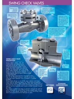
6 Materials Valve type selection determined by Size limitations Cost Availability Service32 swing check ValveFigure check ValveFigure check ValveFigure check ValveFigure Names1 Body2 Body Cap3 Ball4 Body Seal Gasket5 Seat6 Stem7 Gland Flange8 Stem Packing9 Gland Follower10 Thrust Bearing11 Thrust Washer12 Indicator Stop13 Snap Ring14 Gland Bolt15 Stem Bearing16 Body Stud Bolt & Nuts17 Gland Cover18 Gland Cover Bolts19 HandleFigure ValveFigure Resilient SealSealing Slip38 Valve Selection ProcessGeneral procedure for valve Identify DESIGN information includingpressure and temperature, valve function,material, Identify potentially appropriate valvetypes and components based onapplication and function( , block, throttle, or reverse flowprevention).39 Valve Selection PROCESS ,cont d3. Determine valve application requirements( , DESIGN or service limitations).
7 4. Finalize valve selection. check factors toconsider if two or more valves Provide full technical descriptionspecifying type, material, flange rating, 1 - DetermineRequired Flange Rating Pipe: Flanges:A-182 Gr. F11 DESIGN Temperature: 900 F DESIGN Pressure:375 psigMo21Cr411 41 Exercise 1 - Solution1. Identify material specification of flange A-182 Gr, F112. Determine Material Group No. (Table ) Group Determine class using Table with designtemperature and Material Group No. The lowest class for DESIGN pressure of 375 psig is class 300. class 300 has 450 psig maximum pressure at 900 F42 DESIGN Conditions General Normal operating conditions DESIGN conditions DESIGN pressure and temperature Identify connected equipment and associateddesign conditions Consider contingent conditions Consider flow direction Verify conditions with PROCESS engineer43 Loading ConditionsPrincipal pipe load types Sustained loads Act on SYSTEM all or most of time Consist of pressure and total weight load Thermal expansion loads Caused by thermal displacements Result from restrained movement Occasional loads Act for short portion of operating time Seismic and/or dynamic loading44 Stresses Produced ByInternal PressureSltPScScSltP====Longitudinal StressCircumferential (Hoop)
8 StressWall ThicknessInternal PressureFigure Categorization Primary Stresses Direct Shear Bending Secondary stresses Act across pipe wall thickness Cause local yielding and minor distortions Not a source of direct failure46 Stress Categorization, cont d Peak stresses More localized Rapidly decrease within short distance oforigin Occur where stress concentrations andfatigue failure might occur Significance equivalent to secondary stresses Do not cause significant distortion47 Allowable StressesFunction of Material properties Temperature Safety factorsEstablished to avoid: General collapse or excessive distortion fromsustained loads Localized fatigue failure from thermalexpansion loads Collapse or distortion from occasional AllowableStresses in TensionTable Allowable Stress S, ksi. At Metal Temperature, No/Grade1002003004005006007008009001000 110012001300 14001500 Carbon SteelA 106 - MoA 335 - MoA 335 P11 - 8Ni pipeA 312TP304 - 12Ni-2 MopipeA 312TP316 Thickness RequiredFor Internal Pressure P = DESIGN pressure, psigD = Pipe outside diameter, = Allowable stress in tension, psiE = Longitudinal-joint quality factorY = Wall thickness correction factor )PYSE(2 PDt++++====CAttm++++==== (or Type)DescriptionEjCarbon SteelAPI5L.
9 Seamless pipeElectric resistance welded pipeElectric fusion welded pipe, double butt, straight orspiral seamFurnace butt 53 Type SType EType FSeamless pipeElectric resistance welded pipeFurnace butt welded 106..Seamless and Intermediate Alloy SteelA 333..Seamless pipeElectric resistance welded 335..Seamless SteelA 312..Seamless pipeElectric fusion welded pipe, double butt seamElectric fusion welded pipe, single butt 3581, 3, 452 Electric fusion welded pipe, 100% radiographedElectric fusion welded pipe, spot radiographedElectric fusion welded pipe, double butt and Nickel AlloyB 161..Seamless pipe and 514..Welded 675 AllWelded , FMaterials900 & lower9501000105011001150 & ..52 Curved and Mitered Pipe Curved pipe Elbows or bends Same thickness as straight pipe Mitered bend Straight pipe sections welded together Often used in large diameter pipe May require larger thickness Function of number of welds, conditions, size53 Sample Problem 2 -Determine Pipe Wall ThicknessDesign temperature: 650 FDesign pressure: 1,380 outside diameter: 14 : ASTM A335, Gr.
10 P11 ( ),seamlessCorrosion allowance: 54 Sample Problem 2 - Solution)PYSE(2 PDt++++====(((())))(((())))[[[[]]]] ,11200,16214380,1t==== ++++ ====55 Sample Problem 2 -Solution, cont dtm = t + c = + = Branch ConnectionFigure ReinforcementZone LimitsReinforcementZone LimitsA1A3A4A4A2A2A3 Pipe C57 Reinforcement Aread1 = Effective length removed from run pipe, = Branch outside diameter, = Minimum branch thickness, = Corrosion allowance, in. ========= Acute angle between branch and header ====sin)cT(2 Ddbb158 Required Reinforcement AreaRequired reinforcement area, A1:Where: th = Minimum required header thickness, in.)sin2(dtA1h1 ====59 Reinforcement Pad Provides additional reinforcement Usually more economical than increasingwall thickness Selection variables Material Outside diameter Wall thicknessrbp4 Tsin)DD(A ====60 Sample Problem 3 Pipe material: Seamless, A 106/Gr.