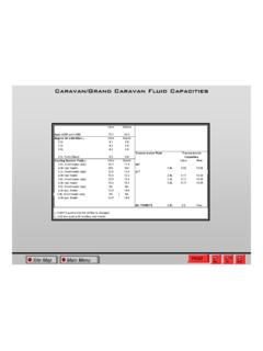
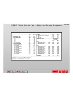
Transcription of SYSTEM DESIGN RECOMMENDATIONS - Ram …
1 2016 ProMaster DESIGN RECOMMENDATIONS SYSTEM DESIGN RECOMMENDATIONS FUEL SYSTEMS Any modification of fuel tanks, lines, hoses or connectors is the complete responsibility of the second stage manufacturer. The responsibility for determining compliance to F/CMVSS 301 regulations is that of the Final Stage Manufacturer. To verify F/CMVSS compliance, vehicle testing may be required. Questions regarding compliance with F/CMVSS regulations should be directed to your legal counsel, the National Highway Traffic Administration or Transport Canada. WARNING: Always refer to the ProMaster Service Manual before servicing any portion of the fuel SYSTEM . Fuel rail pressure must be released before opening any fuel SYSTEM . Welding around or near fuel SYSTEM components is not recommended.
2 Shield or remove components as required to protect them from heat and weld splatter. Modification of the fuel tank, its location, lines, hoses, evaporative systems can affect F/CMVSS 301 SYSTEM compliance. If the final stage manufacturer modifies any portion of the fuel SYSTEM , they assume the full SYSTEM responsibility. AUXILIARY FUEL PORT An auxiliary fuel tap is provided on gas and diesel fuel tanks to provide fuel for secondary power systems. This is located on top of the fuel pump module and is sealed with a connector. It is designed with barbed end to accept a hose and clamp. This SYSTEM will not drain the vehicle fuel completely. There will be sufficient fuel to drive back from the worksite. Utilize due care when installing a secondary fuel SYSTEM .
3 Install a check valve in line to prevent OBD11 SYSTEM faults. Installing a secondary fuel port may affect the vehicles ability to comply with F/CMVSS 301 (gasoline engines ONLY). Refer to the fuel tank filler pipe location attachment section for a picture of the port. Final stage manufacturer assumes all responsibility for fuel SYSTEM modifications and SYSTEM compliance. EXHAUST SYSTEMS Modifying the exhaust SYSTEM is not recommended as it may affect F/CMVSS emissions certification. Do not remove any original equipment exhaust SYSTEM components. Never add components to the SYSTEM that increases back pressure. Do not remove OEM clamps or hangers. Final stage manufacturer assumes all responsibility for exhaust SYSTEM modifications and SYSTEM compliance.
4 NOTE: Never remove heat shields provided as original equipment. It is also the final stage manufacturer s responsibility to install appropriate shielding to any secondary body or equipment installed onto the Chassis. Final stage / individual manufacturers assume all responsibility related to modifications performed. Page 1 of 9 2016 ProMaster DESIGN RECOMMENDATIONS COOLING SYSTEM Do not modify original equipment cooling SYSTEM , fan, fan clutch, hoses and routing or the shroud. Do not install secondary equipment that blocks the grill opening forward of the radiator. Doing so could result in unsatisfactory cooling SYSTEM performance. Refer to ProMaster service manual for proper SYSTEM fill procedures and service. BODY DESIGN RECOMMENDATIONS FINISHING ELEMENTS If a different mat from the original is used on the floor of the driver s side, it must not interfere with the excursion of the pedals (accelerator, brake) limiting their travel.
5 ENGINE COMPARTMENT When making a conversion to the vehicle front end body sheet metal (example: for a motor home) the front radiator grill must be designed to ensure at least the same passage of air as the original, as on the version with the same chassis cab. Correct engine cooling must also be ensured, as on the original vehicle, making no changes to the inlet air permeability area, which must be no lower than that defined and visible on the version with similar cab. When necessary, it is also recommended to implement an air flow duct, such as, for instance, the one in the attached diagram, in order to allow a regular flow toward the radiator. No alterations or additional elements must be made to the areas of the engine that emit most heat.
6 ( shields) Page 2 of 9 2016 ProMaster DESIGN RECOMMENDATIONS Dynamic Flow WITHOUT Conveyance on Radiator, Intercooler and Air Inlet Cross Member INDICATIONS FOR MODIFYING FRONT Technical specifications of intake air permeability surface in engine bay on basic vehicles. Page 3 of 9 2016 ProMaster DESIGN RECOMMENDATIONS If modifications to the vehicle front are required, the air permeability surface must be uniformly distributed, maintaining the values used on the original version, over the areas corresponding to the radiator (see diagram below). Warning: failure to observe the indications provided may result in serious engine damage FITTING A ROOF RACK The ProMaster roof contains unique attachments in the roof that allow the mounting of Mopar or aftermarket roof racks.
7 The roof rack must be fitted using the attachments on the roof, following the instructions of the roof rack manufacturer. Maximum admissible load condition (including roof rack) must not be exceeded. Short wheelbase - 150 Kg Medium wheelbase - 150 Kg Long wheelbase - 150 Kg NOTE: The limit of 25 kg for each attachment on the roof must not be exceeded. The maximum permitted weight of 150 kg is an absolute limit, even if the wheelbase is lengthened. Page 4 of 9 2016 ProMaster DESIGN RECOMMENDATIONS Diagram of Roof Rack Attachment 7 - Top Exterior 8 - Roof 9 - Roof Rack Pin 10 - Roof Rack Attachment Reinforcement X0 - Front Wheel Axis Attachment P ositioning Page 5 of 9 2016 ProMaster DESIGN RECOMMENDATIONS Page 6 of 9 2016 ProMaster DESIGN RECOMMENDATIONS OPENING A HATCH IN THE ROOF A hatch may be opened in the roof, providing that the SYSTEM does not involve cutting the internal body reinforcements and the sealing and structural integrity of the roof is maintained.
8 The figure below shows an installation example. 1 - Sealant 2 - Cut area 3 - Attachment profile 4 - Hatch NOTE: If the hatch has to be opened in a different area of the roof (a), cutting of the structural ribs (b) is not permitted. The structure integrity of the roof must be maintained. Page 7 of 9 2016 ProMaster DESIGN RECOMMENDATIONS MAKING A WINDOW IN THE SIDE It is permitted to make one or more side windows, provided that they are not on the structural pillars. If it is necessary to make the window at the structure, the opening must comprise a frame around the window that is connected to the original pillars and longitudinal members (see solution B) in order to restore the structural rigidity of the body shell. A - Original Solution B - Solution with Added Peripheral Frame.
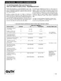
9 Make the cut as shown in the diagram, taking care to maintain a perimeter profile with minimum width of: 15 mm for windows fitted with rubber seal (fig. C); 20 or 25 mm for bonded windows (fig. D);1 - Pillar 2 Seal 3 - Glass. 1 Pillar 2 - Bonding Material 3 - Glass. Page 8 of 9 2016 ProMaster DESIGN RECOMMENDATIONS FLOOR/WALL T IE DOWN RINGS The rings on the floor are tested to support 225 lbs. static load The rings on wall are tested to support 70lbs. Static load The rings are attached to the floor or wall with 29 N-m of torqueHVAC TECHNICAL SPECIFICATIONSW eight (Kg.) Air inflow rate (Stdm3/h) (VENT Max Cold) Max. Power Absorption (Amps @12V) (VENT max cold) Climate Control SYSTEM 405 <25 Air Flow Rate (Stdm3/h) Engine Coolant Flow Rate (1/h) Thermal Power (BTU/h) Installed Mass Thermal Power (kW) Heating SYSTEM 400 800 36,200 500 34,150 Air Flow Rate (Stdm3/h) Thermal Power (BTU/h) Evaporator Thermal Power Installed (kW) AC SYSTEM 400 20,500 AC COOLANT LINE AUX PORT LOCATIONS Yellow - Gas Green - Diesel Page 9 of 9