Transcription of Systems I: Computer Organization and Architecture
1 Systems I: Computer Organization and ArchitectureLecture 10: Microprogrammed ControlMicroprogramming The control unit is responsible for initiating the sequence of microoperations that comprise instructions. When these control signals are generated by hardware, the control unit is hardwired. When these control signals originate in data stored in a special unit and constitute a program on the small scale, the control unit is memory The control function specifying a microoperation is a binary variable whose active state could be either 1 or 0. In the variable s active state, the microoperation is executed.
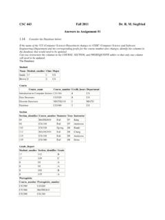
2 The string of control variables which control the sequence of microoperations is called a control word. The microoperations specified in a control word is called a microinstruction. Each microinstruction specifies one or more microoperations that is performed. The control unit coordinates stores microinstruction in its own memory (usually ROM) and performed the necessary steps to execute the sequences of microinstructions (called microprograms).The Microprogrammed Control Unit In a microprogrammed processor, the control unit consists of: Control address register contains the address of the next microinstruction to be executed.
3 Control data register contains the microinstruction to be executed. The sequencer determines the next address from within control memory Control memory where microinstructions are Control OrganizationExternalinputNext-addressgen erator(sequencer)ControladdressregisterC ontrolMemory(ROM)ControldataregisterCont rolwordNext-address informationSequencer The sequencer generates a new address by: incrementing the CAR loading the CAR with an address from control memory. transferring an external addressor loading an initial address to start the control Sequencing Microinstructions are usually stored in groups where each group specifies a routine, where each routine specifies how to carry out an instruction.
4 Each routine must be able to branch to the next routine in the sequence. An initial address is loaded into the CAR when power is turned on; this is usually the address of the first microinstruction in the instruction fetch routine. Next, the control unit must determine the effective address of the The next step is to generate the microoperations that executed the instruction. This involves taking the instruction s opcode and transforming it into an address for the the instruction s microprogram in control memory. This process is called mapping. While microinstruction sequences are usually determined by incrementing the CAR, this is not always the case.
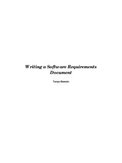
5 If the processor s control unit can support subroutines in a microprogram, it will need an external register for storing return Sequencing (continued) When instruction execution is finished, control must be return to the fetch routine. This is done using an unconditional branch. Addressing sequencing capabilities of control memory include: Incrementing the CAR Unconditional and conditional branching (depending on status bit). Mapping instruction bits into control memory addresses Handling subroutine calls and Of Address For Control MemoryInstruction CodeMappingLogicMultiplexersControl Address Register(CAR)Control MemoryBranchLogicSubroutineRegister(SBR) IncrementerMUXselectStatusbitsSelect astatus bitBranch addressMicrooperationsClocksubroutine returnext microopcond & Branching Status bits provide parameter information such as the carry-out from the adder, sign of a number, mode bits of an instruction, etc.
6 Control the conditional branch decisions made by the branch logic together with the field in the microinstruction that specifies a branch Logic Branch Logic -may be implemented in one of several ways: The simplest way is to test the specified condition and branch if the condition is true; else increment the address register. This is implemented using a multiplexer: If the status bit is one of eight status bits, it is indicated by a 3-bit select number. If the select status bit is 1, the output is 0; else it is 0. A 1 generates the control signal for the branch; a 0 generates the signal to increment the CAR.
7 Unconditional branching occurs by fixing the status bit as always being of Instruction Branching to the first word of a microprogram is a special type of branch. The branch is indicated by the opcode of the instruction. The mapping scheme shown in the figure allows for four microinstruction as well as overflow space from 1000000 to From Instruction Code To Microoperation Address1 0 1 1address0 1 0 1 1 0 0 Mapping bits:0 x x x x0 0 Microinstructionaddresss:Subroutines Subroutine calls are a special type of branch where we return to one instruction below the calling instruction.
8 Provision must be made to save the return address, since it cannot be written into Hardware ConfigurationMUXAR100PC100 Memory2048 x 16 MUXDR150AC150 ALSUCAR60 SBR60 Control memory128 x 20 Computer InstructionsIOpcodeAddress100111415AC M[EA],M[EA] AC0011 EXCHANGEM[EA] AC0010 STOREIF (AC > 0)THEN PC EA0001 BRANCHAC AC + M[EA]0000 ADDD escriptionOpcodeSymbolMicroinstruction Code Format (20 bits)F2F1F3 CDBRADF1, F2, F3 : Microoperation FieldCD: Condition For BranchingBR: Branch FieldAD: Address FieldSymbols and Binary Code For Microinstruction FieldsWRITEM[AR] DR111 PCTARAR PC110 DRTARAR DR(0-10)101 DRTACAC DR100 INCACAC AC + 1011 CLRACAC 0010 ADDAC AC + DR001 NOPNone000 SymbolMicrooperationF1 Symbols and Binary Code For Microinstruction Fields (continued)PCTDRDR(0-10) PC111 INCDRDR DR + 1110 ACTDRDR AC101 READDR M[AR]100 ANDAC AC DR011 ORAC AC DR010 SUBAC AC-DR001 NOPNone000 SymbolMicrooperationF2 Symbols and Binary Code For Microinstruction Fields (continued)
9 Reserved111 ARTPCPC AR110 INCPCPC PC + 1101 SHRAC shr AC100 SHLAC shl AC011 COMAC AC 010 XORAC AC DR001 NOPNone000 SymbolMicrooperationF3 Symbols and Binary Code For Microinstruction Fields (continued)Zero value in ACZAC = 011 Sign bit of ACSAC(15)10 Indirect Address bitIDR(15)01 Unconditional BranchUAlways = 100 CommentsSymbolConditionCDSymbols and Binary Code For Microinstruction Fields (continued)CAR(2-5) DR(11-14), CAR(0, 1, 6) 0 MAP11 CAR SBR (return from subroutine)RET10 CAR AR, SBR CAR + 1 if cond. = 1 CAR CAR + 1 if condition = 0 CAL01 CAR AR if condition = 1 CAR CAR + 1 if condition = 0 JMP00 FunctionSymbolBRSymbolic Microinstructions It is possible to create a symbolic language for microcode that is machine-translatable to binary code.
10 Each line define a symbolic microinstruction with each column defining one of five fields: Label-Either blank or a name followed by a colon (indicates a potential branch) Microoperations-One, Two, Three Symbols, separated by commas (indicates that the microoperation being performed) CD-Either U, I, S or Z (indicates condition) BR-One of four two-bit numbers AD-A Symbolic Address, NEXT (address), RET, MAP (both of these last two converted to zeros by the assembler) (indicates the address of the next microinstruction) We will use the pseudoinstruction ORG to define the first instruction (or origin)